Aerodynamic characteristic measuring device capable of automatically adjusting distance between upper and lower rotors of Mars aircraft
A technology of aerodynamic characteristics and measurement device, which is applied in the simulation device of space navigation conditions, space shuttle, transportation and packaging, etc., can solve the problems such as the inability to realize the measurement of lift-drag characteristics of the dual-rotor system, and achieves reasonable design size coordination and structural design. Scientific and reasonable, novel structure effect
- Summary
- Abstract
- Description
- Claims
- Application Information
AI Technical Summary
Problems solved by technology
Method used
Image
Examples
specific Embodiment approach 1
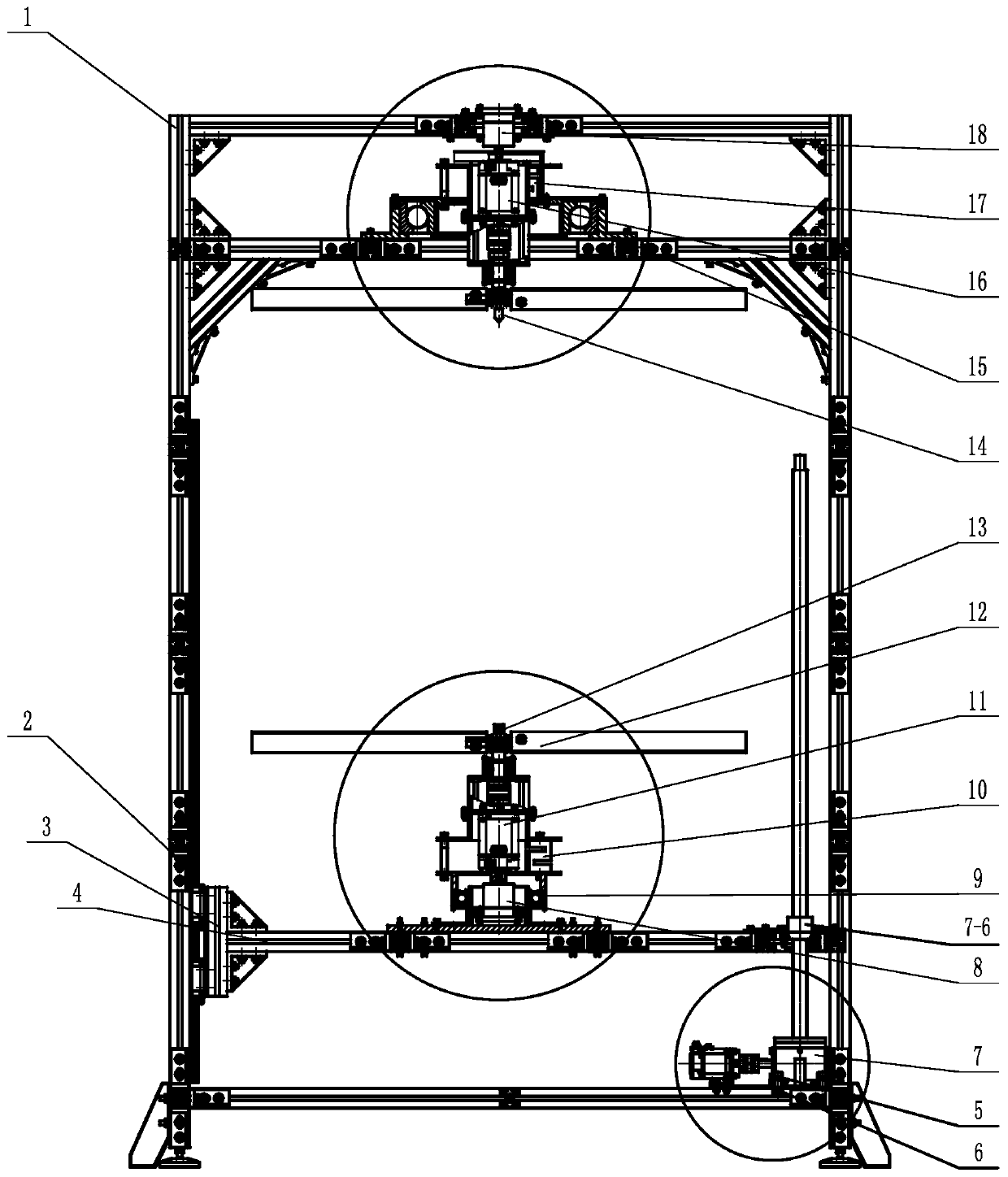
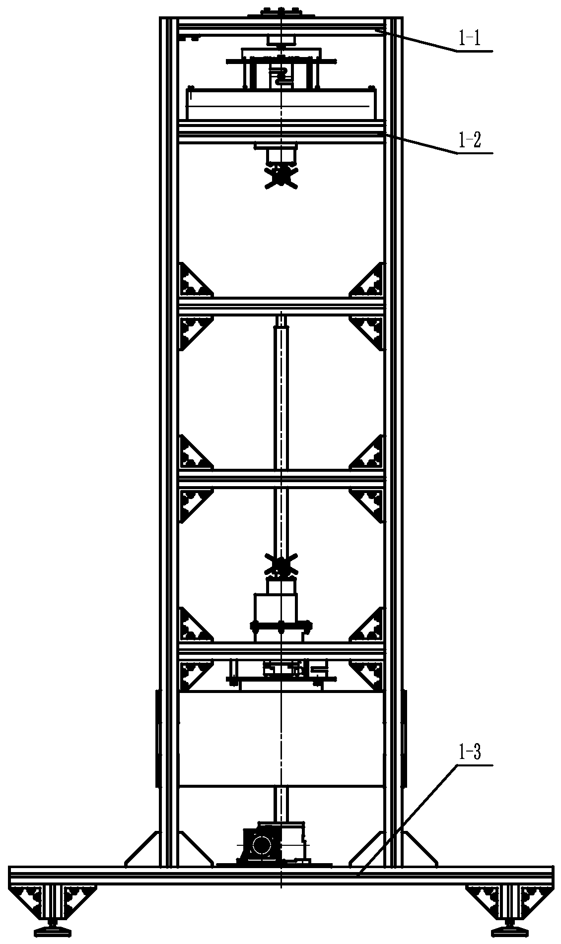
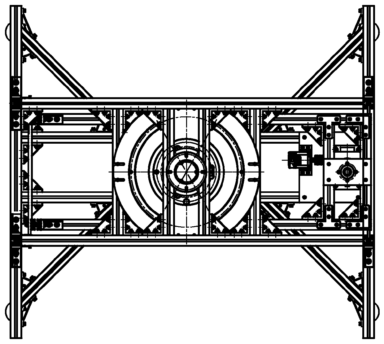
[0030] Specific implementation mode one: combine Figure 1 to Figure 3Describe this embodiment, the aerodynamic characteristic measuring device that the distance between the upper and lower rotors of the Mars spacecraft is automatically adjustable, the device includes a frame 1, an up and down lifting slide mechanism, an upper rotor mechanism and a lower rotor mechanism;
[0031] The up and down lifting slide mechanism is installed inside the frame 1, the lower rotor mechanism is installed on the up and down lifting slide mechanism, and the upper rotor mechanism is installed on the frame 1 top, and the upper rotor mechanism and the lower rotor mechanism are relatively arranged.
[0032] In this embodiment, the frame 1 is located at the outermost layer, which reduces the influence of the rotor boundary layer effect, has a simple structure and high rigidity, and realizes the basic positioning of the lift-drag characteristic measuring device of the rotor system of the split Mars a...
specific Embodiment approach 2
[0033] Specific implementation mode two: combination Figure 1 to Figure 3 Describe this embodiment. This embodiment is to further limit the up and down lifting slide mechanism described in the first specific embodiment. In this embodiment, the up and down lifting slide mechanism includes a movable bracket 4, a lifting module 7, two Guide rail 2 and two slider assemblies 3, each guide rail 2 is fixed on the side wall of the frame 1, each guide rail 2 is provided with a slider assembly 3, and each slider assembly 3 slides with a guide rail 2 Connection, one end of the movable support 4 is fixedly connected with the two slider assemblies 3, and the other end of the movable support 4 is rotatably connected with the lifting module 7. Other compositions and connection methods are the same as those in the second embodiment.
[0034] In this embodiment, the guide rail 2, the slider assembly 3, and the movable bracket 4 constitute a sliding workbench with the function of moving up an...
specific Embodiment approach 3
[0035] Specific implementation mode three: combination Figure 5 Describe this embodiment. This embodiment is to further limit the movable support 4 described in the second specific embodiment. In this embodiment, the movable support 4 includes a slide table 4-1 and a lower rotor housing 4-2. , the lower rotor housing 4-2 is fixed on the upper surface of the slide table 4-1 by bolts, one end of the slide table 4-1 is fixedly connected with the two slide block assemblies 3, and the other end of the slide table 4-1 is connected with the lift Module 7 is connected by rotation. Other compositions and connection methods are the same as those in the second embodiment.
PUM
 Abstract
Description
Claims
Application Information
 - Generate Ideas
- Intellectual Property
- Life Sciences
- Materials
- Tech Scout
- Unparalleled Data Quality
- Higher Quality Content
- 60% Fewer Hallucinations
Browse by: Latest US Patents, China's latest patents, Technical Efficacy Thesaurus, Application Domain, Technology Topic, Popular Technical Reports.
© 2025 PatSnap. All rights reserved.Legal|Privacy policy|Modern Slavery Act Transparency Statement|Sitemap|About US| Contact US: help@patsnap.com


