Gravity sewage discharging mechanism of train excrement collecting system and vacuum excrement collecting system
A sewage discharge mechanism and waste collection technology, which is applied in railway car body parts, sanitary equipment, transportation and packaging, etc., can solve the problems of inability to use the waste collection system, inconvenient maintenance, complex structure, etc., and achieves a simple overall structure and reduced maintenance. Cost, effect of simplified structure
- Summary
- Abstract
- Description
- Claims
- Application Information
AI Technical Summary
Problems solved by technology
Method used
Image
Examples
Embodiment 1
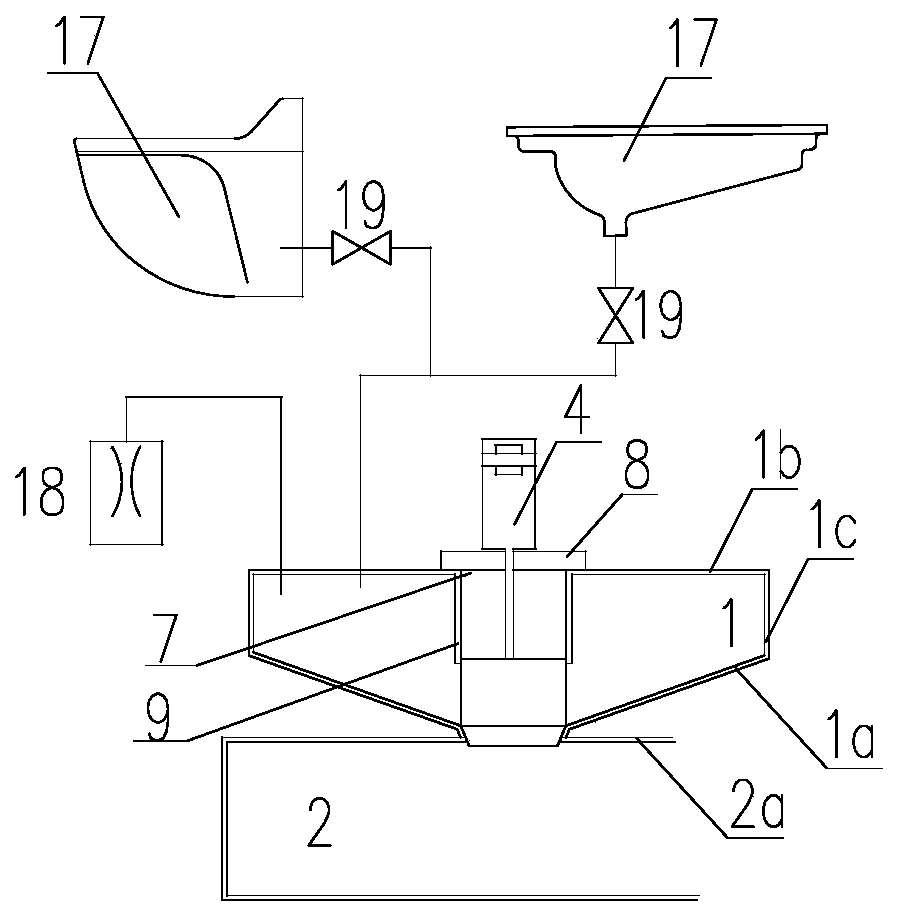
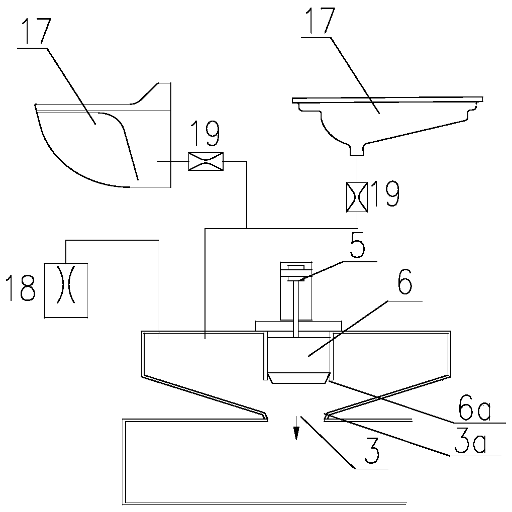
[0035] Such as figure 1 and figure 2 As shown, in the present embodiment, a gravity sewage discharge mechanism of a feces collection system for trains is provided, comprising a transfer box 1 and a dirt box 2, the transfer box 1 is placed above the dirt box 2, and the bottom plate 1a of the transfer box 1 is in contact with the dirt box 2. The top plate 2a of the material box 2 is connected through the communication port 3, and the valve 4 for controlling the connection of the communication port 3 is installed at the communication port 3, and the dirt and waste water entering the transfer box 1 are discharged to the lower part by gravity. In the dirt box 2.
[0036] The communication port 3 is formed by docking the opening on the bottom plate 1a of the transfer box 1 and the opening on the top plate 2a of the dirt tank 2, and the transfer box 1 and the dirt tank 2 are fastened by flanges at the corresponding openings. The devices are fixedly connected together, which is con...
Embodiment 2
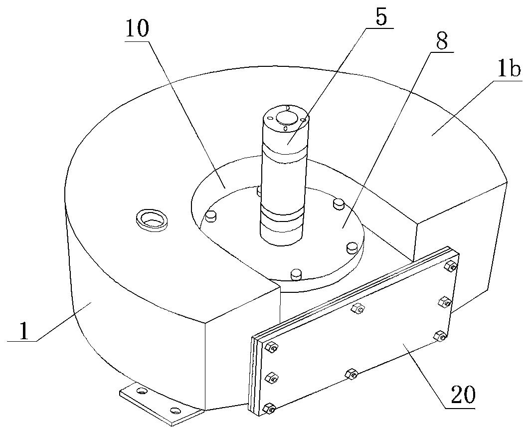
[0052] Such as image 3 As shown, the top plate 1b of the revolving box 1 is a flat plate structure, and the top plate 1b can be one of circular, square, semicircular, elliptical, fan-shaped, image 3 The top plate 1b shown in the figure adopts a semicircular structure, and the difference from the first embodiment is that in this embodiment, there is a downwardly recessed part on the top plate 1b, and the setting position of the recessed part 10 is not limited, as long as It only needs to be arranged facing the communicating port 3 , and the driving mechanism 5 is installed on the top plate 1 b in the recessed portion 10 . Setting the recessed part 10 on the top plate 1b is beneficial to further reduce the installation height of the driving mechanism 5 on the premise of ensuring the capacity of the transfer box 1 , and it is also beneficial to shorten the stroke of the valve plug 6 .
[0053] The bottom plate 1a of the transfer box 1 is also a conical structure protruding dow...
Embodiment 3
[0055] Such as Figure 4 and Figure 5 As shown, the difference from Embodiment 1 or Embodiment 2 is that in this embodiment, a second opening 11 is provided on the top plate 1b of the transfer box 1, and a closed valve plug cavity is provided above the second opening 11. 12. The valve plug 6 protrudes into the interior of the transfer box 1 when it is in the blocked state, and moves upward to be accommodated in the valve plug cavity 12 when it is in the open state. The driving mechanism 5 is fixed on the housing of the valve plug chamber 12, the valve plug chamber 12 is fixedly connected with the top plate 1b of the transfer box 1 through the second sealing and fixing structure, the second sealing and fixing structure is an annular fixing seat 13, and the fixing seat 13 and the A sealing ring is arranged between the top plates 1b to realize a sealed connection.
[0056] In this structure, the diameter of the second opening 11 matches the diameter of the valve plug 6, and th...
PUM
 Abstract
Description
Claims
Application Information
 - R&D Engineer
- R&D Manager
- IP Professional
- Industry Leading Data Capabilities
- Powerful AI technology
- Patent DNA Extraction
Browse by: Latest US Patents, China's latest patents, Technical Efficacy Thesaurus, Application Domain, Technology Topic, Popular Technical Reports.
© 2024 PatSnap. All rights reserved.Legal|Privacy policy|Modern Slavery Act Transparency Statement|Sitemap|About US| Contact US: help@patsnap.com


