A machining method for a floating gearbox of a self-elevating multifunctional service platform

A service platform and gear box technology, applied in the direction of transmission boxes, components with teeth, etc., can solve the problems of floating gearboxes that are bulky and cannot meet the one-time machining of floating gearboxes, so as to reduce requirements and reduce Improvement of processing time and production efficiency

Active Publication Date: 2021-12-24
招商局邮轮制造有限公司 +1
View PDF6 Cites 0 Cited by
  • Summary
  • Abstract
  • Description
  • Claims
  • Application Information

AI Technical Summary

Problems solved by technology

[0008] 3. The installation end face of the support round hole involves the matching of the gear of the lifting motor and the rack of the leg, so the distance from the installation end face of the support round hole to the center line of the card slot must be guaranteed;
[0010] Due to the large volume of the floating gearbox, with a size of 3520mm (height) x 2300mm (width) x 1200mm (depth), great requirements are placed on the machining stroke of the machining machine tool. The existing conventional milling and boring machines in many shipyards cannot meet the entire floating gearbox. Gearbox one-time machining

Method used


Image

  • A machining method for a floating gearbox of a self-elevating multifunctional service platform
  • A machining method for a floating gearbox of a self-elevating multifunctional service platform
  • A machining method for a floating gearbox of a self-elevating multifunctional service platform

Examples


Embodiment Construction

[0044] The present invention will be further described in detail below through embodiments in conjunction with the accompanying drawings.

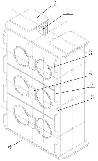
[0045] Please refer to the name of each part of the floating gearbox 6 figure 1 , the machining method of the floating gearbox 6 includes the following operations:

[0046] First, cylinder end processing

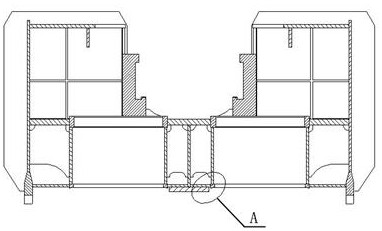
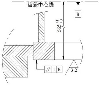
[0047] The spindle of the machine tool measures the machining allowance from the center line of the rack back to the end face of the support hole 3, installs a φ300 milling cutter on the spindle, and processes six end faces at one time to ensure the design size mm, and the end face of the supporting round hole 3 is used as the reference plane for subsequent processing, such as figure 2 , image 3 shown;

[0048] Second, positioning plate 4 processing

[0049] Based on the end face of the supporting round hole 3, the processing amount of the intermediate positioning plate 4 is detected according to the digital display and the depth g...


PUM

PropertyMeasurementUnit
sizeaaaaaaaaaa

Abstract

The invention provides a machining method for a floating gear box of a self-elevating multifunctional service platform, which includes the following steps: machining the end face of a cylinder, machining a positioning plate, machining a motor installation groove and a secondary clamping reference plane, and supporting a round hole End step surface processing, boring processing, marking and scribing, motor slot width and fillet processing, floating gearbox bottom and top surface processing, secondary clamping, gantry milling machine processing. The present invention employs two types of machine tools with limited processing capabilities. In the case that the floating gearbox is horizontal relative to the machine tool, milling and boring are performed on the support round hole on the upper layer of the floating gearbox, and the positioning datum plane is processed. Place the contact surface of the floating gearbox on the equal-height block of the gantry milling machine, clamp it twice, and use the gantry machine to process the wear-resistant plate slot, so that two kinds of machine tools with limited processing capacity can be used to process large-volume The purpose of the floating gearbox is to reduce the requirements on the machining machine tools, while parallel processing improves production efficiency.

Description

technical field [0001] The invention relates to the field of marine engineering equipment, in particular to a machining method for a floating gearbox of a self-elevating multifunctional service platform. Background technique [0002] The self-elevating multifunctional service platform is mainly used for offshore oilfield services, life support and wind power installation. From bottom to top, the platform is mainly composed of spud boots, spud legs, main hull, lifting tower, living building and helicopter deck. Among them, the gearbox is a key component located between the lifting towers and providing power for the whole platform lifting. [0003] The self-elevating multifunctional service platform has 4 lift towers, each lift tower is equipped with 3 sets of gear boxes, and each set of gear boxes is equipped with gears, motors and braking devices. The gearbox is responsible for lifting the platform to a predetermined height to overcome the impact of the harsh marine enviro...

Claims


Application Information

Patent Timeline
Patent Type & Authority Patents(China)
IPC IPC(8): B23P15/00F16H57/02
CPCB23P15/00F16H57/02
Inventor 徐戎李阳张卫孔国照
Owner 招商局邮轮制造有限公司
Why Eureka
Try Eureka