
Lower shell assembly for refrigerator compressor

A technology for refrigerator compressors and components, which is applied to pump components, mechanical equipment, variable-capacity pump components, etc. It can solve problems such as poor fixation of shell components, overheating of internal parts of the compressor, and affecting the overall operation of the compressor. Achieve the effect of preventing poor heat dissipation, prolonging service life, and good anti-corrosion and wear resistance

Inactive Publication Date: 2020-05-05
何俊
View PDF0 Cites 0 Cited by
  • Summary
  • Abstract
  • Description
  • Claims
  • Application Information

AI Technical Summary

Problems solved by technology

It sucks low-temperature and low-pressure refrigerant gas from the suction pipe, drives the piston to compress it through the operation of the motor, and discharges high-temperature and high-pressure refrigerant gas to the exhaust pipe to provide power for the refrigeration cycle. The machine is used to protect the structure of the compressor. The structure design of the existing lower shell assembly for the refrigerator compressor is unreasonable, the shell body assembly is not fixed, and its own strength is poor, which easily affects the overall operation of the compressor. The main body is usually installed in the shell body assembly, resulting in poor heat dissipation inside the compressor, resulting in overheating and damage to the internal parts of the compressor. The existing treatment method is usually to open holes in the shell body assembly, but it is very easy for debris to enter The interior of the compressor affects the overall operation. Therefore, it is urgent for those skilled in the art to design a new type of lower shell assembly for refrigerator compressors.

Method used


Image

  • Lower shell assembly for refrigerator compressor
  • Lower shell assembly for refrigerator compressor

Examples


Embodiment Construction

[0017] The present invention will be further explained below in conjunction with the accompanying drawings and embodiments.

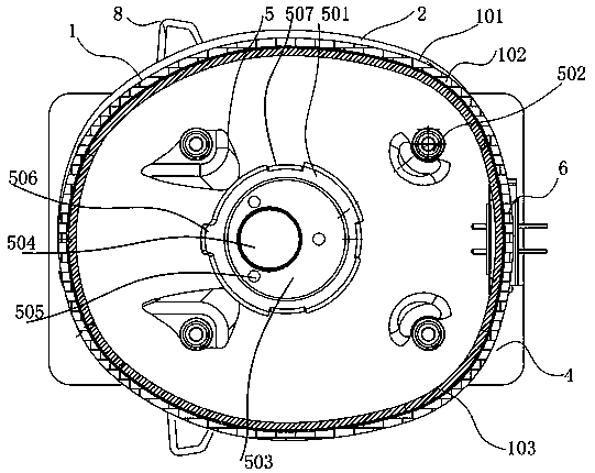
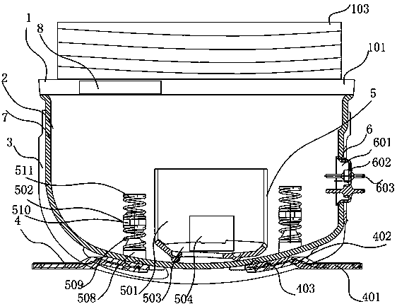
[0018] A lower shell assembly for a refrigerator compressor, comprising a positioning top ring seat assembly 1, a shell body assembly 2, a reinforced protective support 3, a positioning support plate assembly 4, an elastic positioning assembly 5, and a heat dissipation unit assembly 6. The shell body assembly 2 The top is provided with a positioning top ring seat assembly 1 and connected by welding. The inner end of the shell body assembly 2 is bonded with a sound-absorbing and shock-absorbing layer 7. The outer wall of the shell body assembly 2 is welded with a reinforced protective support 3. The positioning support The plate component 4 runs through the through hole on the reinforced protective support 3 and extends inward to the bottom of the shell body component 2. The positioning support plate component 4 is welded to the shell body component 2, an...


PUM


Abstract

The invention discloses a lower shell assembly for a refrigerator compressor. The lower shell assembly comprises a positioning top annular seat component, a shell body component, a reinforced protective support, a positioning support plate component, an elastic positioning component and a radiating unit component, wherein the reinforced protective support is welded to the outer wall of the shell body component and is an integrated forming structure formed through casting stainless steel or alloy, and the stainless steel or alloy is high in strength and excellent in corrosion preventing and wear-resisting performance, so that the shell body component is effectively protected, and the service life of the entire shell body is prolonged; the positioning support plate component penetrates through a through hole in the reinforced protective support, extends inwards to the bottom end of the shell body component and plays the role of fixing the bottom end of the shell body component, so that fixation of the bottom end of the shell body component is ensured; a ventilating pipeline plays a radiating role in the interior of the compressor, so that the situation that poor radiation of the compressor causes damage to internal components is effectively prevented; a filter net is arranged in the ventilating pipeline, and the pore diameter of the filter net is 0.15-0.25 mm, so that the situation that impurities enter the compressor from the ventilating pipeline to affect overall operation is effectively prevented.

Description

technical field [0001] The invention relates to the technical field of refrigerator accessories, in particular to a lower casing assembly for a refrigerator compressor. Background technique [0002] A compressor is a driven fluid machine that elevates low-pressure gas to high-pressure gas, and is the heart of the refrigeration system. It sucks low-temperature and low-pressure refrigerant gas from the suction pipe, drives the piston to compress it through the operation of the motor, and discharges high-temperature and high-pressure refrigerant gas to the exhaust pipe to provide power for the refrigeration cycle. The machine is used to protect the structure of the compressor. The structure design of the existing lower shell assembly for the refrigerator compressor is unreasonable, the shell body assembly is not fixed, and its own strength is poor, which easily affects the overall operation of the compressor. The main body is usually installed in the shell body assembly, resul...

Claims


Application Information

Patent Timeline
Patent Type & Authority Applications(China)
IPC IPC(8): F04B39/12F04B39/14F04B39/16F04B39/06G10K11/16
CPCF04B39/0033F04B39/06F04B39/121F04B39/14F04B39/16G10K11/16
Inventor 何俊
Owner 何俊
Learn More