
Conveying device for communication equipment production

A technology of conveying device and communication equipment, applied in the direction of conveyor objects, transportation and packaging, etc., can solve the problems of inability to guarantee movement stability, falling damage of communication devices, and high labor intensity of workers, so as to avoid accidental falling damage, The effect of force balance and labor intensity reduction

Inactive Publication Date: 2020-05-05
陕西联智网络科技有限公司
View PDF6 Cites 1 Cited by
  • Summary
  • Abstract
  • Description
  • Claims
  • Application Information

AI Technical Summary

Problems solved by technology

[0004] The purpose of the present invention is to provide a conveying device for the production of communication equipment to solve the problem of the existing conveying device for the production of communication equipment. When the communication devices are conveyed on the conveyor belt, it is necessary to manually take out the unqualified communication devices to avoid mixing qualified products. Among them, the existing simple grabbing tool needs to manually adjust the position of the suction cup, which is inconvenient to use; the existing conveying device for communication equipment production cannot guarantee the time when the unqualified communication device is picked up by the simple grabbing tool. The stability of communication devices is easy to be accidentally dropped and damaged, and the products are repeatedly moved to the defective product box, resulting in high labor intensity for workers; the existing conveying device for communication equipment production needs post-processing after screening unqualified products. Workers specialize in the collection of finished products, the process is cumbersome and the work efficiency is low

Method used


Image

  • Conveying device for communication equipment production
  • Conveying device for communication equipment production
  • Conveying device for communication equipment production

Examples


Embodiment Construction

[0029] The technical solutions of the present invention will be clearly and completely described below in conjunction with the embodiments. Apparently, the described embodiments are only some of the embodiments of the present invention, not all of them. Based on the embodiments of the present invention, all other embodiments obtained by persons of ordinary skill in the art without creative efforts fall within the protection scope of the present invention.

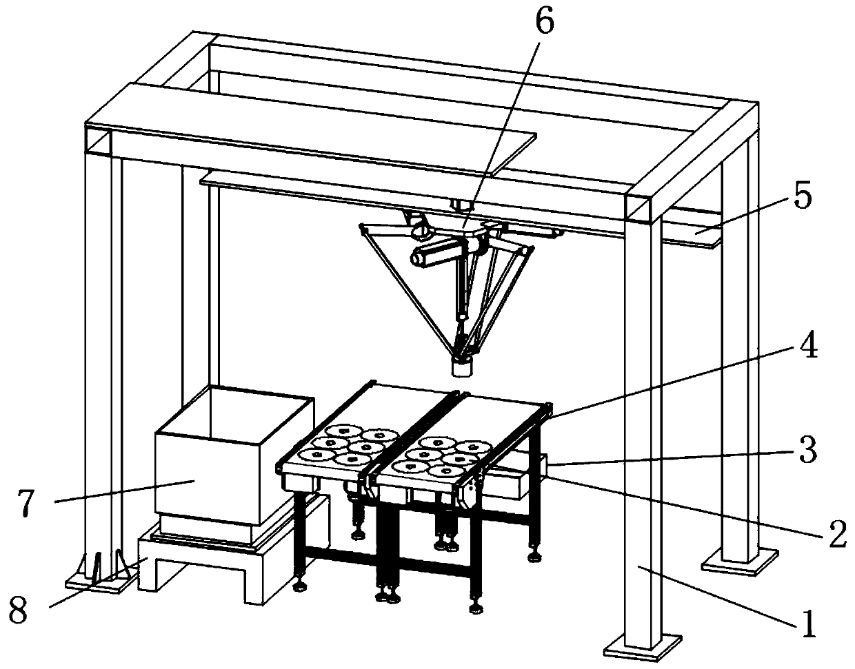
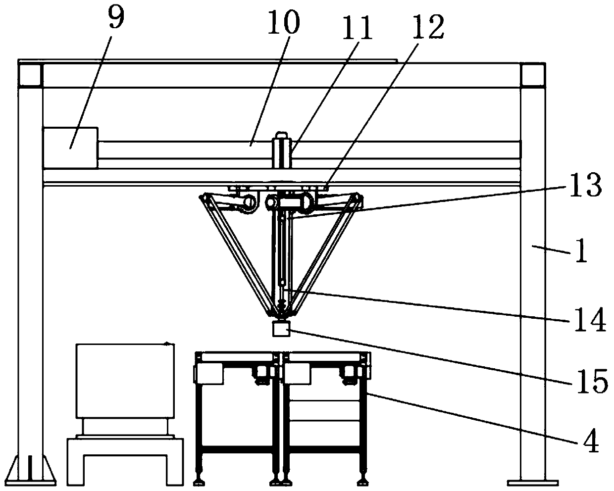
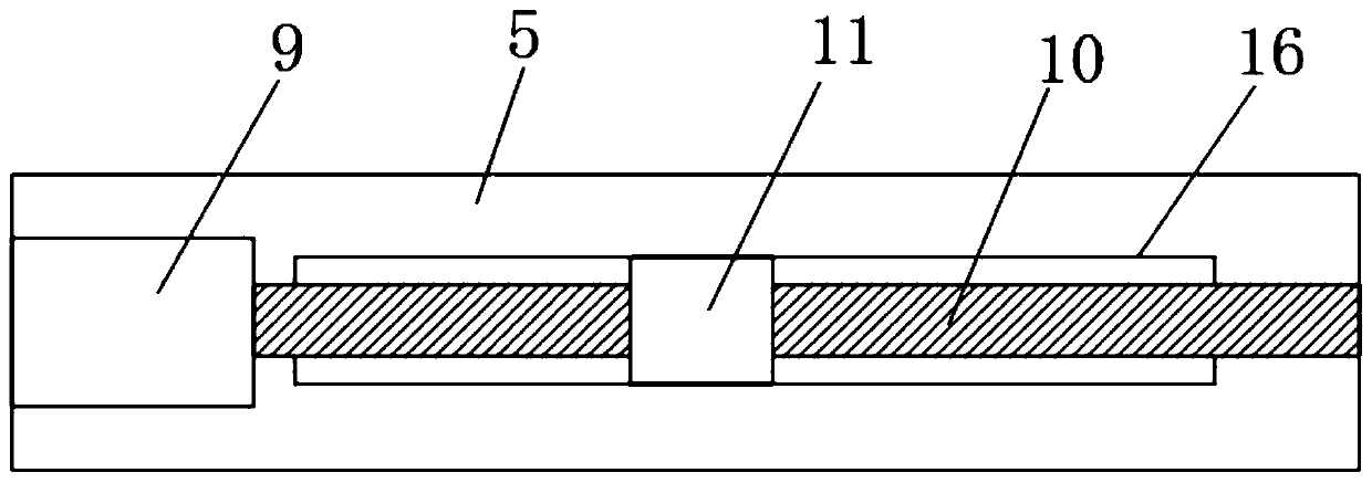
[0030] Such as Figure 1-5 As shown, a conveying device for communication equipment production includes a mounting frame 1 and a conveyor belt 4. Two conveyor belts 4 are arranged below the mounting frame 1 near the middle, and several communication devices 2 are placed on the two conveyor belts 4 respectively. , one end of the two conveyor belts 4 is provided with a finished product box 3, and one side of the conveyor belt 4 adjacent to the finished product box 3 is provided with a base 8, the top of the base 8 is fixedly ...


PUM


Abstract

The invention discloses a conveying device for communication equipment production. The conveying device for communication equipment production comprises an installation frame and conveying belts, wherein two conveying belts are arranged at a position close to the middle part, below the installation frame; a plurality of communication devices are placed on the two conveying belts separately; a finished product box is arranged at one end of the two conveying belts; a base is arranged at one side of the conveying belt which is adjacent to the finished product box; and an inferior-quality productbox is fixedly arranged at the top of the base. Output ends of three second motors are controlled to drive three rotary rods to rotate simultaneously, the three rotary rods rotate simultaneously and clockwise, pull rods in three directions push a pull disc to move downwards, a suction disc is enabled to make contact with the communication devices, the suction disc is fixed, then the three second motors are controlled to reversely rotate simultaneously, and grabbing working for unqualified communication devices is realized; and because three vertical plates are uniformly distributed on the bottom surface of a fixed plate, the stress of the suction disc is balanced, so that the stability during movement is improved, and the unqualified devices do not need to be manually pick up by workers, so that the labor intensity of the workers is reduced, and damage to the communication devices due to accidental falling is avoided.

Description

technical field [0001] The invention relates to the field of communication equipment production equipment, in particular to a conveying device for communication equipment production. Background technique [0002] Existing communication devices need to use transmission equipment during the production process, and workers need to screen the communication equipment during the transmission process. [0003] In the existing conveying device for the production of communication equipment, when the communication devices are conveyed on the conveyor belt, it is necessary to manually take out the unqualified communication devices to avoid being mixed into the qualified products. The existing simple grabbing tools need to manually adjust the position of the suction cup. It is inconvenient to use; the existing conveying device for communication equipment production cannot guarantee the stability during movement when unqualified communication devices are picked up by simple grasping tool...

Claims


Application Information

Patent Timeline
IPC IPC(8): B65G47/91
CPCB65G47/912
Inventor 郭淑霞
Owner 陕西联智网络科技有限公司
Learn More