Cold shrink outdoor terminal pre-molding mixing device

A terminal and pre-mixing technology, which is applied in the field of mixing devices before molding, can solve problems such as material sticking, incomplete discharge, and mixing red interference, etc., and achieve the effects of low equipment cost, reduced usage, and strong energy saving

Inactive Publication Date: 2020-05-05
顾建荣
View PDF4 Cites 0 Cited by
  • Summary
  • Abstract
  • Description
  • Claims
  • Application Information

AI Technical Summary

Problems solved by technology

However, after the mixing is completed, when the material needs to be released, the material will stick to the stirring rod or other structures, resulting in incomplete discharge, and will interfere with the next mixing process.

Method used


Image

  • Cold shrink outdoor terminal pre-molding mixing device
  • Cold shrink outdoor terminal pre-molding mixing device
  • Cold shrink outdoor terminal pre-molding mixing device

Examples


Embodiment 1

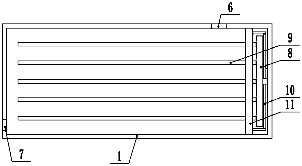
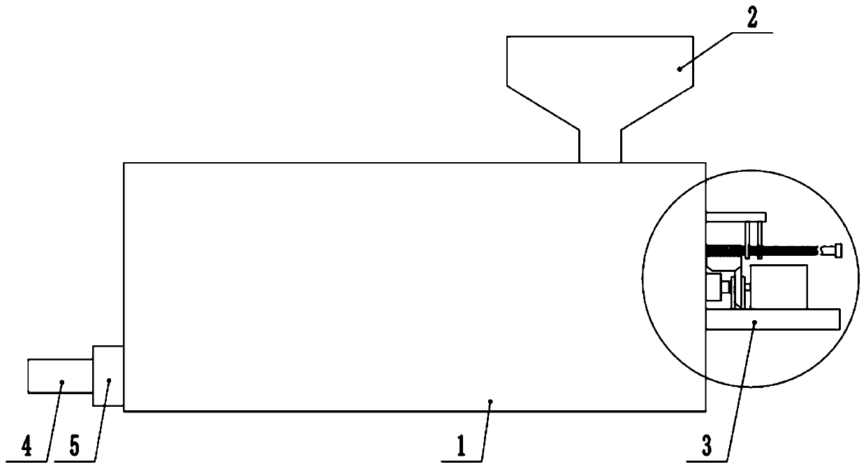
[0028] see Figure 1-5 , a pre-molding mixing device for cold-shrinkable outdoor terminals, including a mixing box 1, one end of the top of the mixing box 1 is fixedly connected to a feed hopper 2, and the mixing box 1 is provided with a stirring mechanism and a pushing mechanism, One end outside the mixing box 1 is provided with a driving device 3 for driving the stirring mechanism and the pushing mechanism, and the end of the mixing box 1 away from the driving device 3 is fixedly connected to the discharge pipe 4, and the discharge pipe 4 is provided with The discharge valve 5, the top and the side of the mixing box 1 are respectively provided with a feed inlet 6 and a discharge outlet 7 corresponding to the feed hopper 2 and the discharge pipe 4.

[0029] The stirring mechanism includes a turret 8 arranged at one end of the mixing box 1 , and one side of the turret 8 is fixedly connected with a plurality of stirring rods 9 .

[0030] The pushing mechanism includes a push p...

Embodiment 2

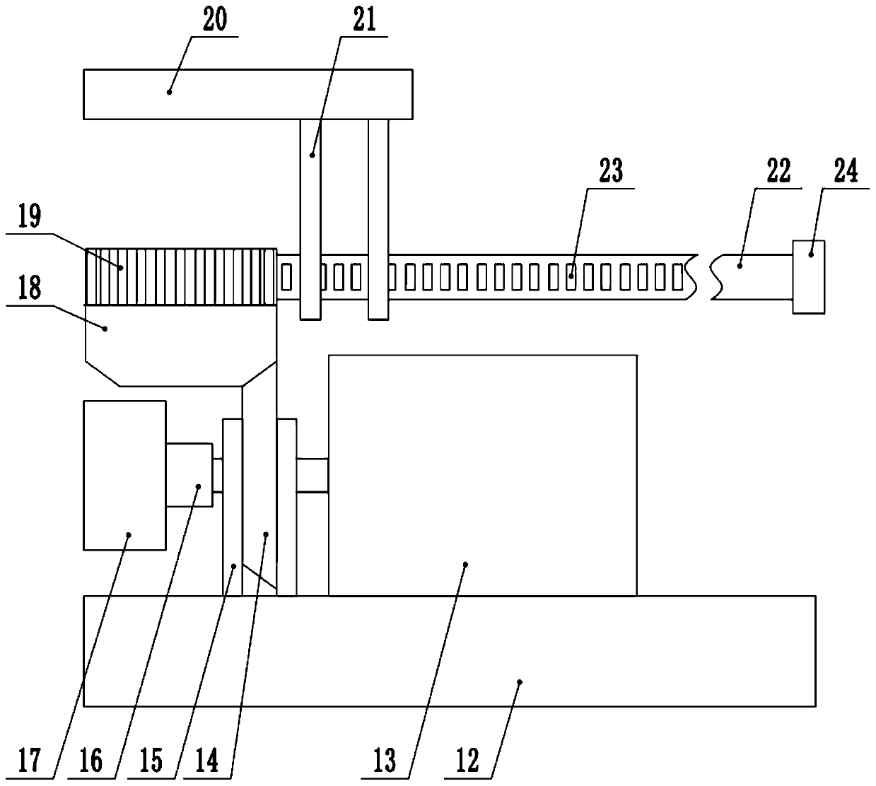
[0035] see Figure 1-5, the other content of this embodiment is the same as that of Embodiment 1, the difference is that: the end of the mixing box 1 above the fixed seat 12 is fixedly connected to the top fixed seat 2012, and the bottom end of the top fixed seat 2012 is fixedly connected to a plurality of fixed plate 21 , the moving rod 22 runs through the fixed plate 21 . One end of the moving rod 22 away from the pushing frame 10 is fixedly connected to a limit end block 24 .

[0036] In the implementation process of the present invention, the material is first poured into the mixing box from the feed hopper 2, and then the driving motor is started, and the driving motor drives the locking device 17 outside the fixed sleeve 16 to rotate, so that the stirring rod inside the mixing box 1 9 Rotate to stir the material. After the stirring is completed, control the locking device 17 in the first cone wheel 14 to lock, and the drive motor 13 drives the first cone wheel 14 to rot...


PUM


Abstract

The invention discloses a cold shrink outdoor terminal pre-molding mixing device and relates to the technical field of cable cold shrink material production. The cold shrink outdoor terminal pre-molding mixing device comprises a mixing tank. One end of the top of the mixing tank is fixedly connected with a feed hopper. The mixing tank is internally provided with a stirring mechanism and a pushingmechanism. One end of the exterior of the mixing tank is provided with a driving device used for driving the stirring mechanism and the pushing mechanism. The end, far away from the driving device, ofthe mixing tank is fixedly connected with a discharge pipe. A discharge valve is arranged on the discharge pipe. The top end and one side of the mixing tank are provided with a feed port and a discharge port corresponding to the feed hopper and the discharge pipe respectively. The cold shrink outdoor terminal pre-molding mixing device can conduct stirring and mixing on materials through the stirring mechanism, can comprehensively output the mixed materials through the pushing mechanism to prevent material residues, can drive the stirring mechanism and the pushing mechanism through one drivingmotor through a locking device, reduces the number of adopted motors and is high in energy-saving performance and low in equipment cost.

Description

technical field [0001] The invention relates to the technical field of production of cable cold-shrinkable materials, in particular to a pre-molding mixing device for cold-shrinkable outdoor terminals. Background technique [0002] Optical cables are manufactured to meet optical, mechanical or environmental performance specifications. It is a communication cable assembly that uses one or more optical fibers placed in a sheath as a transmission medium and can be used individually or in groups. The optical cable is mainly composed of optical fiber (glass filament as thin as hair), plastic protective sleeve and plastic sheath. There is no metal such as gold, silver, copper and aluminum in the optical cable, and generally has no recycling value. An optical cable is a communication line in which a certain number of optical fibers form a cable core in a certain way, and is covered with a sheath, and some are also covered with an outer sheath to realize optical signal transmission....

Claims


Application Information

Patent Timeline
Patent Type & Authority Applications(China)
IPC IPC(8): B29B7/16B29B7/22B29B7/26
CPCB29B7/16B29B7/22B29B7/26
Inventor 顾建荣
Owner 顾建荣
Why Eureka
Try Eureka