Methods for remediating contaminated soil and groundwater

A technology for polluted soil and groundwater, applied in the restoration of polluted soil, contaminated groundwater/leachate treatment, water/sewage treatment, etc. The effect of natural degradation, shortened repair time, and low operating cost

Active Publication Date: 2020-05-05
CHINA PETROLEUM & CHEM CORP +1
View PDF10 Cites 6 Cited by
  • Summary
  • Abstract
  • Description
  • Claims
  • Application Information

AI Technical Summary

Problems solved by technology

CN103447291B discloses a method for strengthening gas-phase extraction and restoration of chlorobenzene-contaminated soil. The method includes adopting a plurality of heating extractors, condensing units, gas-liquid separators and vacuum pumps arranged in an equilateral triangle or a square, etc., in a short period of time. The remediation effect of chlorobenzene-contaminated soil is obvious, and the removal rate of pollutants is high, but the effect is easily affected by soil properties, etc. (for example, high soil viscosity, poor heat transfer effect)
CN102513347A discloses a method for treating polluted soil with in-situ thermal intensification combined with soil gas phase extraction technology. The method forms a certain form of heating well in the polluted area, deploys heater components in the heating well, and installs casings. The medium is filled with a catalyst to accelerate the pyrolysis of pollutants into simple small molecular substances; this method has a good treatment effect on pollutants, but the cost of the extraction device is high and it is difficult to popularize
In addition, since volatile and semi-volatile organic compounds are often difficult to dissolve in water and migrate slowly with groundwater, using PRB or extraction treatment technology directly downstream of the polluted area is not only time-consuming and labor-intensive, but also cannot fundamentally solve the pollution problem in the polluted area

Method used


Image

  • Methods for remediating contaminated soil and groundwater

Examples


Embodiment approach

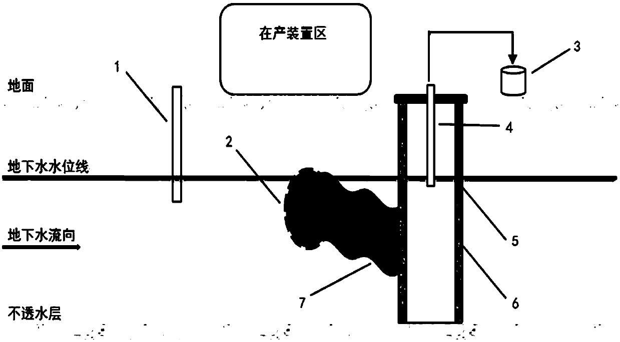
[0020] In the present invention, the injection well is built upstream of the groundwater in the polluted area, and is used to inject the biosurfactant slurry into the groundwater, so that the biosurfactant migrates into the polluted area along with the groundwater. When constructing the injection well, the depth of the well should be dug below the groundwater level. The present invention has no special limitation on the specific construction method and specification of the injection well, which can be selected with reference to the prior art. According to one embodiment, the diameter of the injection well is 5-10 cm.

[0021] In the present invention, the pollutants in the polluted area comprise volatile and / semi-volatile organic compounds. Specific examples of the pollutants include, but are not limited to, one or more of diesel, gasoline, benzene, toluene, di-n-octyl phthalate, and benzo(a)pyrene.

[0022] Preferably, the biosurfactant is selected from at least one of rham...

Embodiment 1

[0041] Diesel leakage from a buried pipeline at a gas station caused pollution. Before this method was implemented, the total petroleum hydrocarbon (C10-C40) content in the soil in the polluted area was 17439 mg / kg, which exceeded the screening value for the second-class land use in GB36600-2018 4500mg / kg, the benzene content of groundwater is 402μg / L, exceeding the conventional index limit of 120μg / L for Class IV water in GB / T14848-2017. The total petroleum hydrocarbon (C10-C40) content in the soil at the collection ditch was 5591 mg / kg, and the benzene content in the groundwater was 57.1 μg / L.

[0042] Build an injection well upstream of the groundwater in the polluted area. The diameter of the injection well is 5cm. Build a collection ditch downstream of the groundwater in the polluted area. The width of the formed collection ditch is 1m, and the length is longer than the scope of the pre-repaired pollution plume. The depth is dug to the impermeable layer , one side of the ...

Embodiment 2

[0046] The ground pipeline buried in a sewage pool leaked, causing the sewage containing dioctyl phthalate to seep into the ground. Before implementing this method, in the polluted area, the content of dioctyl phthalate in the soil was 5617mg / kg. Exceeding the screening value of 2812mg / kg for Class II land use specified in GB36600-2018, the content of dioctyl phthalate in groundwater is 554μg / L, exceeding the unconventional index limit of 300μg / L for Class IV water in GB / T14848-2017 L. The content of di-n-octyl phthalate in the soil at the collection ditch was 4124 mg / kg, and the content of di-n-octyl phthalate in the groundwater was 472 μg / L.

[0047] Build an injection well upstream of the groundwater in the polluted area. The diameter of the injection well is 10cm. Build a collection ditch downstream of the groundwater in the polluted area. The width of the formed collection ditch is 1.2m, the length is longer than the scope of the pre-repaired pollution plume, and the dept...


PUM

PropertyMeasurementUnit
widthaaaaaaaaaa

Abstract

The invention relates to the technical field of soil remediation, in particular to a method for remediating contaminated soil and underground water. The method comprises the steps that (1) an injection well is built on the upstream of underground water in a polluted area, a collecting ditch is built on the downstream of the underground water in the polluted area, wherein pollutants in the pollutedarea comprise volatile and/or semi-volatile organic matters; and (2) a biosurfactant slurry is injected into the injection well to enable the biosurfactant to migrate to the polluted area under the action of underground water, and enable an obtained oil-water mixed solution to enter the collecting ditch to obtain an upper-layer oil phase and a lower-layer water phase. According to the method, thevolatile and semi-volatile organic matters in the polluted soil and underground water can be effectively removed; compared with the existing extraction method and PRB method, the method provided by the invention has the characteristics of high treatment efficiency and simple operation, and is especially suitable for repairing sites which cannot be excavated, extracted and injected above the polluted area.

Description

technical field [0001] The invention relates to the technical field of soil remediation, in particular to a method for remediating polluted soil and groundwater. Background technique [0002] The soil environment is one of the basic elements of the ecosystem, and the basis for the survival and development of human beings and organisms. With the development of my country's industrialization process, environmental pollution accidents and human health damage incidents occur from time to time. At present, volatile and semi-volatile organic pollutants have become the most common and prominent types of pollutants in the soil of industrial sites. Especially sudden environmental pollution accidents, such as oil storage tank leaks, oil pipeline ruptures, gasoline and diesel spills, etc. will cause varying degrees of pollution to soil and groundwater, and further bring greater harm to human health in the site. harm. [0003] The remediation methods for volatile and semi-volatile or...

Claims


Application Information

Patent Timeline
Patent Type & Authority Applications(China)
IPC IPC(8): B09C1/02B09C1/08C02F9/04C02F103/06
CPCB09C1/02B09C1/08B09C2101/00C02F1/40C02F1/722C02F2103/06
Inventor 李博伟王岽冯婕王亭胡艳华
Owner CHINA PETROLEUM & CHEM CORP
Why Eureka
Try Eureka