
Display panel and display device

A technology of display panel and light-emitting layer, applied in printing image acquisition, instrument, calculation, etc., can solve the problems of aging display brightness, affecting display effect, unevenness, etc.

Active Publication Date: 2020-05-01
BOE TECH GRP CO LTD +1
View PDF6 Cites 0 Cited by
  • Summary
  • Abstract
  • Description
  • Claims
  • Application Information

AI Technical Summary

Problems solved by technology

[0003] The present application expects to provide a display panel and a display device, which are used to solve the problems in the prior art that a fingerprint identification area is set in the display area, which affects the display effect, and causes severe local aging and uneven display brightness.

Method used


Image

  • Display panel and display device
  • Display panel and display device
  • Display panel and display device

Examples


Embodiment Construction

[0023] The application will be further described in detail below in conjunction with the accompanying drawings and embodiments. It should be understood that the specific embodiments described here are only used to explain related inventions, rather than to limit the invention. It should also be noted that, for ease of description, only parts related to the invention are shown in the drawings.

[0024] It should be noted that, in the case of no conflict, the embodiments in the present application and the features in the embodiments can be combined with each other. The present application will be described in detail below with reference to the accompanying drawings and embodiments.

[0025] Each of the switch tubes below can be a transistor, and each transistor can be a thin film transistor or a field effect transistor or other devices with the same characteristics. It can be an N-type transistor or a P-type transistor. The use of different types of transistors mainly considers...


PUM


Abstract

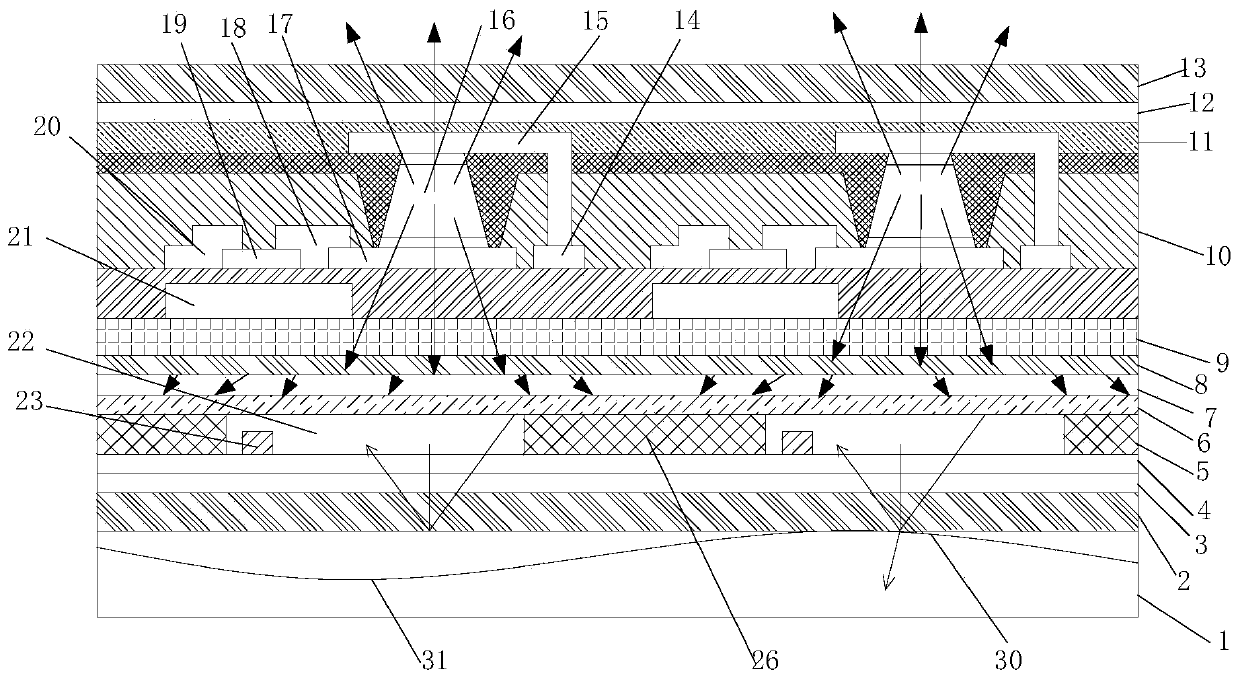
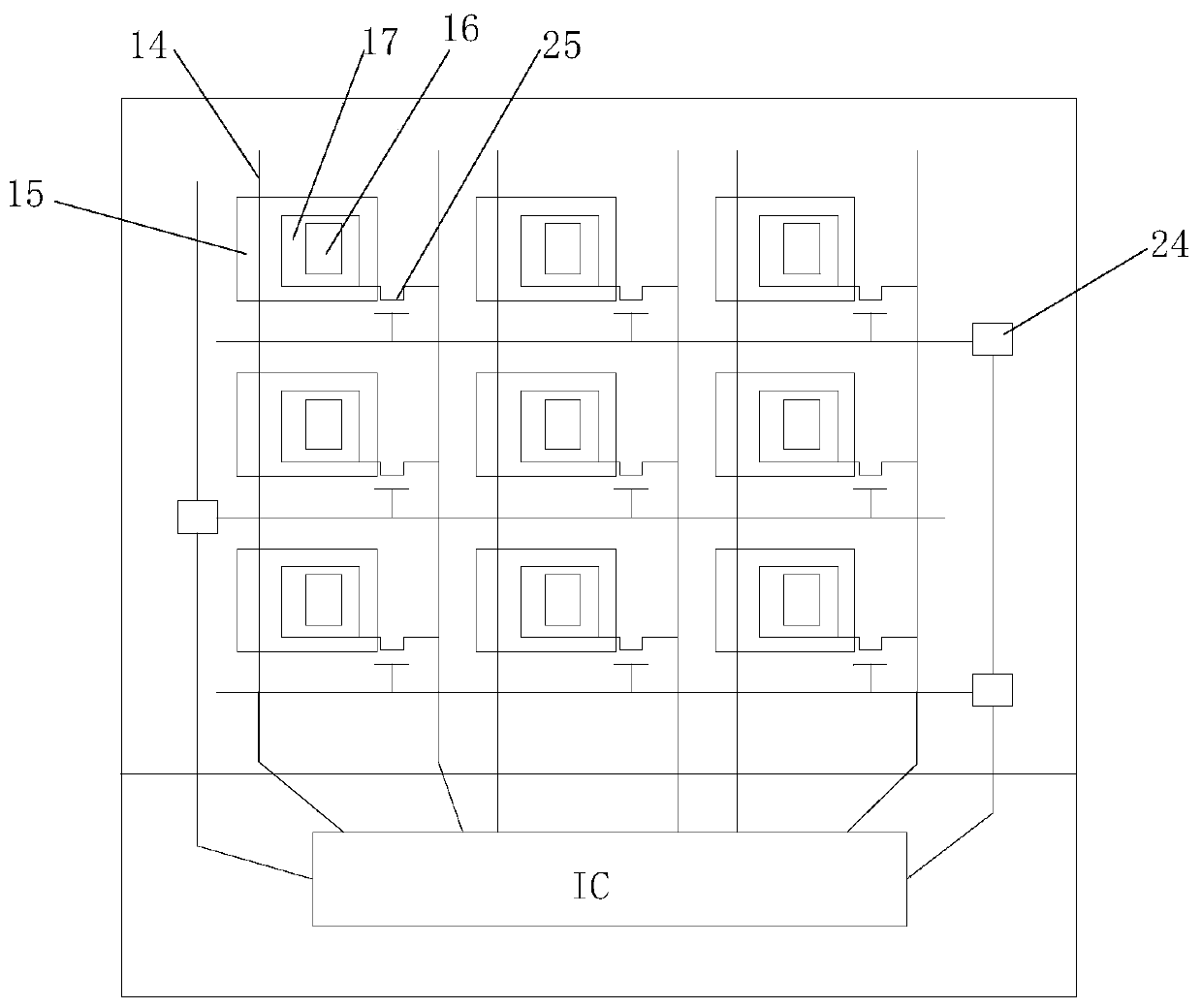
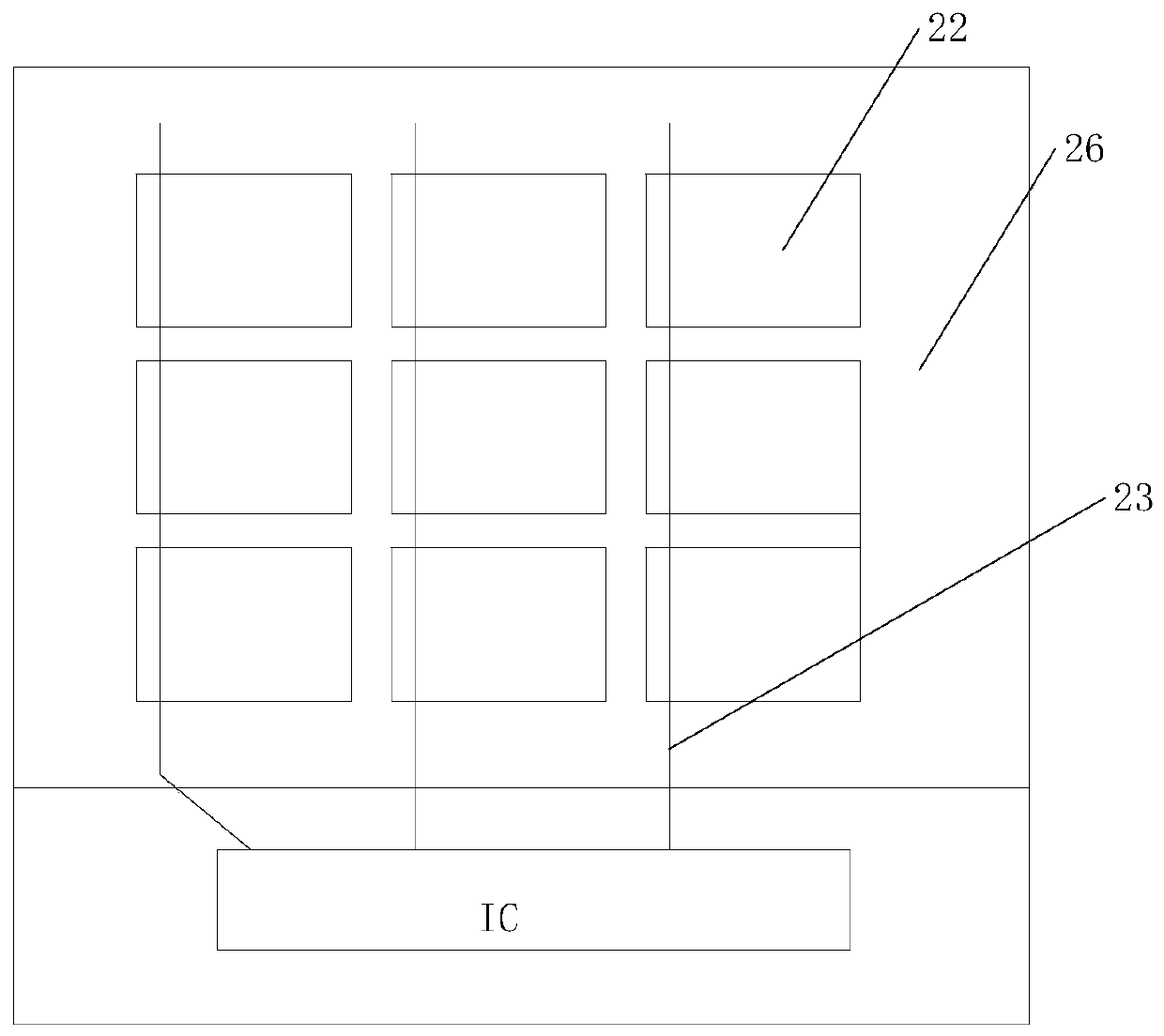
The invention discloses a display panel and a display device. The display panel comprises a light-emitting layer, wherein opposite light-out directions are formed at two sides of the light-emitting layer, and a light-guiding layer and a sensing layer are sequentially arranged in a stacked mode in one light-out direction; the light-guiding layer is used for emitting light, which is emitted by the light-emitting layer to the light-guiding layer, to the sensing layer at a predetermined angle; and the sensing layer comprises multiple first light-transmitting regions and first light-shading regionssurrounding the corresponding first light-transmitting regions, and each first light-transmitting region is provided with a photosensitive element. According to the scheme, the light-emitting layer has the two opposite light-out directions, one of the light-out directions serves as a display surface, and the other light-out direction serves as a light source for fingerprint recognition; and during fingerprint recognition, it is needless to perform highlighting display on a local region, thus, aging of a specific region cannot be intensified, and the problem of non-uniform luminance caused bylocal aging does not exist. Besides, fingerprint recognition and picture display are realized at the two sides respectively, and therefore an adverse influence cannot be imposed on display.

Description

technical field [0001] The present invention generally relates to the field of display technology, and in particular to a display panel and a display device. Background technique [0002] Under-screen fingerprint recognition is an emerging fingerprint recognition technology, which is to set the fingerprint recognition area in the predetermined display area of ​​the display screen, set the photosensitive element in the fingerprint recognition area, and set the display area of ​​the photosensitive element on the display screen when performing fingerprint recognition. The brightness is increased to provide enough light to irradiate the user's finger, so that the photosensitive element receives enough light reflected by the finger for fingerprint recognition. When fingerprint recognition is required, the brightness of the area where the photosensitive element is set needs to be increased, which affects the display effect. In addition, because the area of ​​the photosensitive ele...

Claims


Application Information

Patent Timeline
Patent Type & Authority Applications(China)
IPC IPC(8): G02F1/157G02F1/153G06K9/00
CPCG02F1/157G02F1/153G06V40/1318
Inventor 邹浩伟李鑫陈伟雄李玲李阳恒
Owner BOE TECH GRP CO LTD
Learn More