Eccentric chain wheel transmission device
An eccentric sprocket and transmission technology, applied in transmission, belt/chain/gear, mechanical equipment, etc., can solve the problems of difficulty, low overall structural strength, and high cost, achieving low cost and avoiding high cost , to construct simple effects
- Summary
- Abstract
- Description
- Claims
- Application Information
AI Technical Summary
Problems solved by technology
Method used
Image

Examples
Embodiment 1
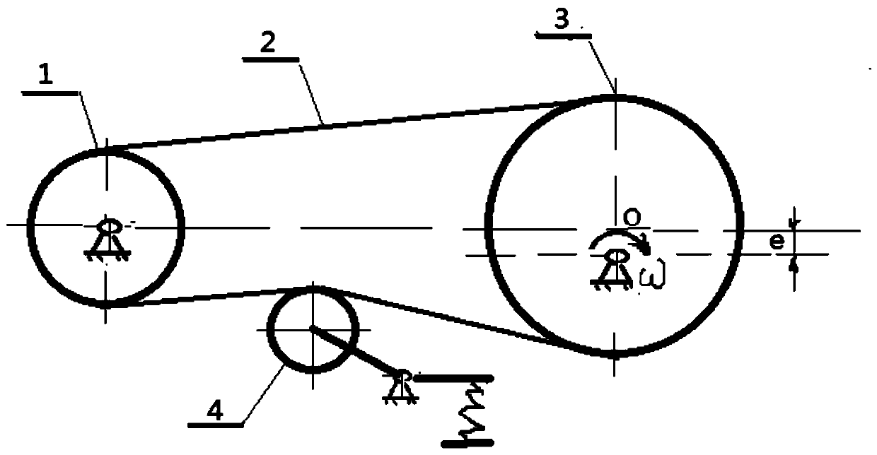
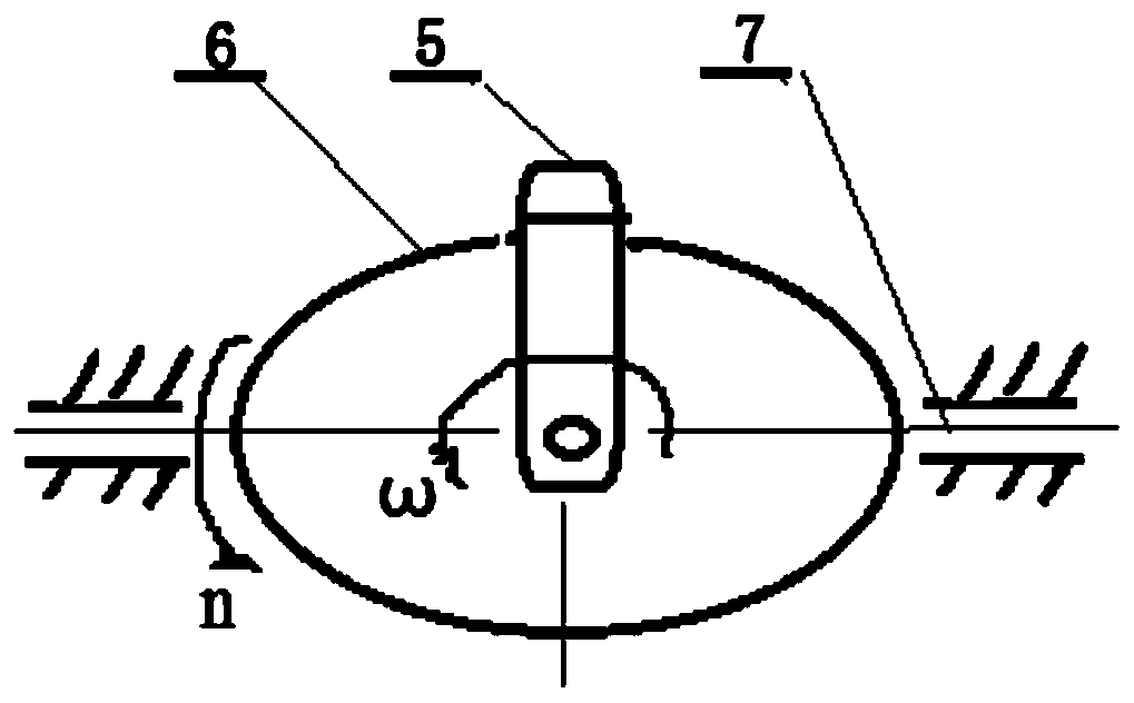
[0034] like figure 1 , Figure 4 , Figure 5 , Image 6 ,as well as Figure 7 A kind of eccentric sprocket transmission device shown, in order to realize chain transmission, comprises chain 2, driving sprocket 1, tensioning pulley 4, and driven sprocket 3 that are sequentially connected through the chain 2; wherein, the The driving sprocket 1 is configured to have a special tooth shape, and is used to provide power to the driven sprocket 3 through the chain 2; the tensioning wheel 4 is configured to have an engaging portion or The fitting friction part is used to adjust the tension of the chain 2; the driven sprocket 3 is configured to have a special tooth shape suitable for the driving sprocket 1 and the chain 2, and is used for according to the The angular velocity of the power output provided by the driving sprocket 1 changes periodically.
[0035] like figure 1 , figure 2 , image 3 ,as well as Figure 7 The e shown in the figure is the eccentricity, ω is the ang...
Embodiment 2
[0039] like figure 1 , Figure 4 , Figure 5 , Image 6 ,as well as Figure 7 The shown eccentric sprocket transmission device, in order to realize chain transmission, includes a chain 2, a driving sprocket 1, a tensioning wheel 4, and a driven sprocket 3 that are sequentially connected through the chain 2; wherein,
[0040] The driving sprocket 1 is configured to have a special tooth shape, and is used to provide power to the driven sprocket 3 through the chain 2;
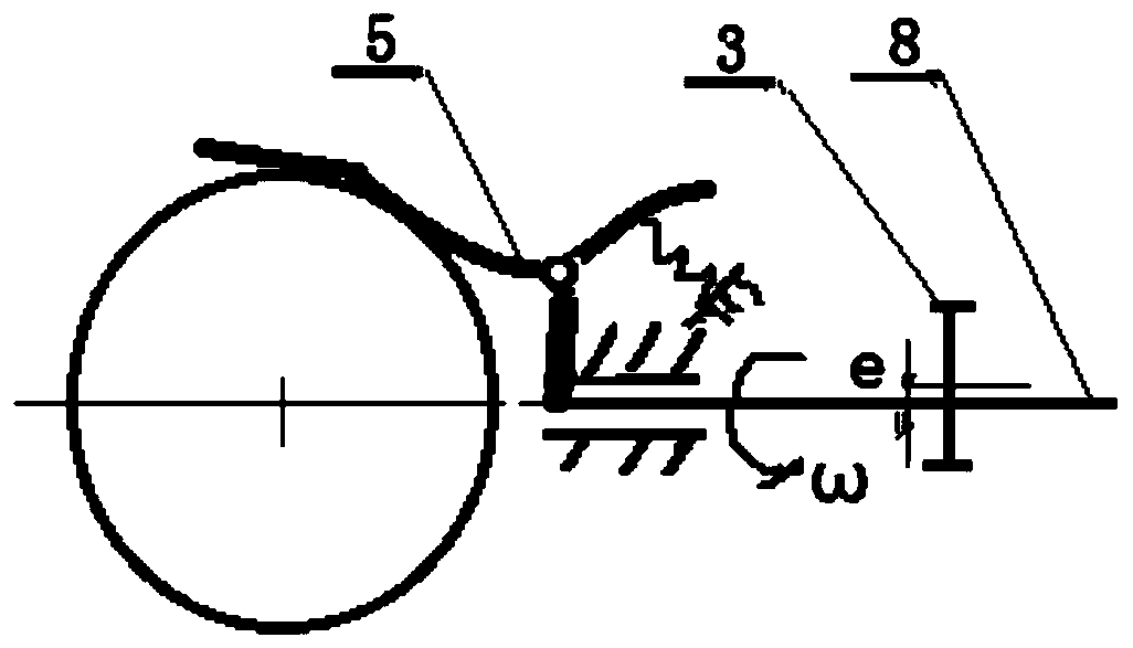
[0041] The tensioning wheel 4 is configured to have an engaging portion or a fitting friction portion compatible with the chain 2 for adjusting the tension of the chain 2; the preferred solution in this embodiment is that the tensioning wheel 4 has an adjusting part configured to automatically adjust the position of the tensioning wheel 4 according to the tension of the chain 2 in motion, so that the tension of the chain 2 is within a preset range. Specifically, such as Figure 5As shown, the tensioning whee...
Embodiment 3
[0050] like figure 1 , Figure 4 , Figure 5 , Image 6 ,as well as Figure 7 The shown eccentric sprocket transmission device, in order to realize chain transmission, includes a chain 2, a driving sprocket 1, a tensioning wheel 4, and a driven sprocket 3 that are sequentially connected through the chain 2; wherein,
[0051] The driving sprocket 1 is configured to have a special tooth shape, and is used to provide power to the driven sprocket 3 through the chain 2;
[0052] The tensioning wheel 4 is configured to have an engaging portion or a fitting friction portion compatible with the chain 2 for adjusting the tension of the chain 2; the preferred solution in this embodiment is that the tensioning wheel 4 has an adjusting part configured to automatically adjust the position of the tensioning wheel 4 according to the tension of the chain 2 in motion, so that the tension of the chain 2 is within a preset range. Specifically, such as Figure 5 As shown, the tensioning whe...
PUM
 Abstract
Description
Claims
Application Information
 - R&D
- Intellectual Property
- Life Sciences
- Materials
- Tech Scout
- Unparalleled Data Quality
- Higher Quality Content
- 60% Fewer Hallucinations
Browse by: Latest US Patents, China's latest patents, Technical Efficacy Thesaurus, Application Domain, Technology Topic, Popular Technical Reports.
© 2025 PatSnap. All rights reserved.Legal|Privacy policy|Modern Slavery Act Transparency Statement|Sitemap|About US| Contact US: help@patsnap.com