Digging and bagging device in earthwork stone engineering and using method thereof

A soil bagging and engineering technology, which is applied in the directions of earth moving machines/shovels, packaging, transportation and packaging, can solve the problems of high labor intensity of engineers, inability to screen the volume of soil blocks, low filling efficiency, etc. Overall work efficiency, intelligent process flow, and the effect of reducing work intensity

Inactive Publication Date: 2020-05-01
马鞍山元辰网络科技有限公司
View PDF12 Cites 1 Cited by
  • Summary
  • Abstract
  • Description
  • Claims
  • Application Information

AI Technical Summary

Problems solved by technology

[0005] 1. In the bagging process of earth and stone works, the existing filling method is to hang the earth and stone bag on the frame so that the top opening of the earth and stone bag faces upwards, and then use an excavator to pour the earth and stone into the bag, and then dig The earth machine lifts the frame, allowing the engineering personnel to remove the earthwork bags filled with earthwork for stacking operations. This bagging method is not only time-consuming and labor-intensive, but also has low bagging efficiency and high labor intensity for engineering personnel;
[0006] 2. Existing earthwork works cannot screen the volume of soil clods during the bagging process, which makes it difficult to bag the soil clods, and when the soil bags are filled with oversized soil clods, the stacking of the soil bags is unstable and blocks The quality of the earth wall cannot be guaranteed, and there are certain risks;
[0007] 3. In the bagging process of the existing earthwork works, the earthbags are filled one by one, resulting in a lot of manpower and low filling efficiency.

Method used


Image

  • Digging and bagging device in earthwork stone engineering and using method thereof
  • Digging and bagging device in earthwork stone engineering and using method thereof
  • Digging and bagging device in earthwork stone engineering and using method thereof

Examples


Embodiment Construction

[0040] The following will clearly and completely describe the technical solutions in the embodiments of the present invention with reference to the accompanying drawings in the embodiments of the present invention. Obviously, the described embodiments are only some, not all, embodiments of the present invention. Based on the embodiments of the present invention, all other embodiments obtained by persons of ordinary skill in the art without making creative efforts belong to the protection scope of the present invention.

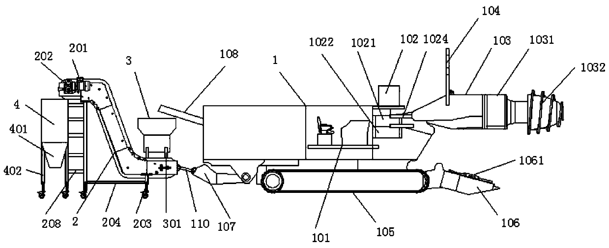
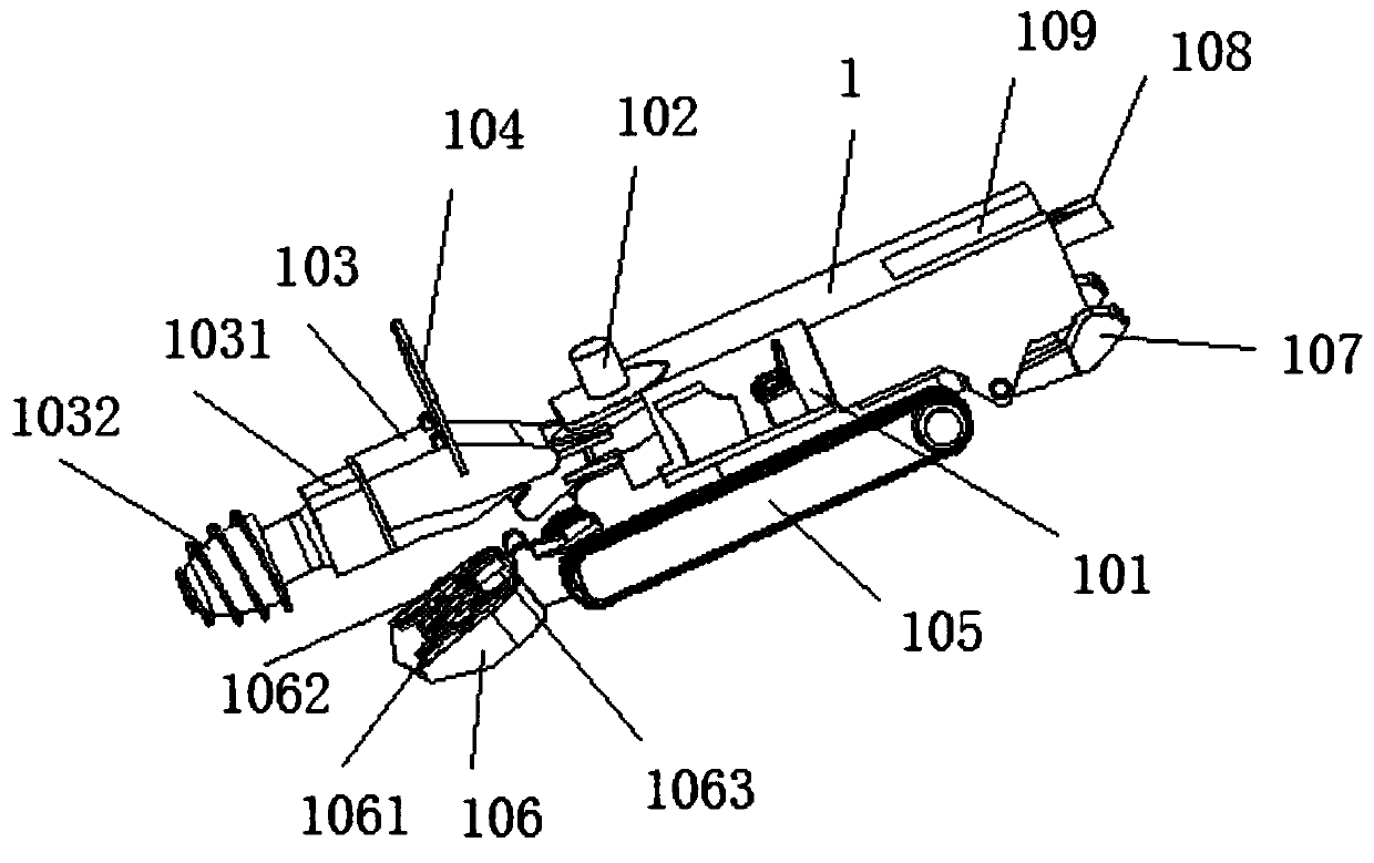
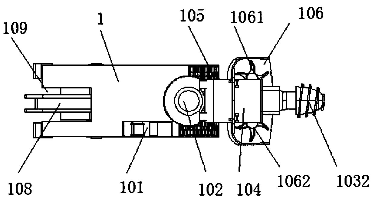
[0041] see Figure 1-10 , in an embodiment of the present invention, an earthmoving bagging device in earthworks, comprising an earthmoving vehicle body 1, a Z-shaped conveying frame 2 and a bagging cavity 4, the rear part of the earthmoving vehicle body 1 passes through a connecting frame 107 By connecting the chain 110 to the side of the starting end of the Z-shaped conveying frame 2, the excavating vehicle body 1 can drive the Z-shaped conveying frame 2 and...


PUM


Abstract

The invention discloses a digging and bagging device in earthwork stone engineering and a using method thereof. The digging and bagging device comprises a digging vehicle body, a Z-shaped conveying frame and bagging cavities. The vehicle tail of the digging vehicle body is fixedly connected with one side of the starting end of the Z-shaped conveying frame through a connecting chain and a connecting frame. The bagging cavities are formed in one side of the conveying tail end of the Z-shaped conveying frame. The digging vehicle body is driven into a soil sampling pit, a second motor inside the soil sampling cavity drives a digging head to rotate, soil blocks are tunneled through a spiral reamer on the conical face of the digging head, and fallen soil blocks are fed into a soil block conveyorbelt, the soil blocks are guided into the bagging cavities through the lifting effect of the Z-shaped conveyor belt, soil bags are bagged through the bagging cavities, soil blocks peeled off from thedigging vehicle body are output through the soil block conveyor belt to fill the soil bags in the digging process of the digging vehicle body, the phenomenon that an excavator is used for secondary digging and bagging in the soil bag bagging process is avoided, the working strength of earthwork stone engineering workers is lowered, and the whole working efficiency of the earthwork stone engineering is improved.

Description

technical field [0001] The invention belongs to the technical field of earthwork bagging, in particular to an earthwork bagging device for earthwork engineering and a method for using the bagging device. Background technique [0002] Earthwork is the general term for earthwork and stonework. The unit of measurement is generally cubic meters. Earthwork engineering includes all aspects of earthwork excavation, filling, transportation, drainage and precipitation. Earthwork generally exists in soil and stone excavation projects. middle. [0003] Earthwork works include the excavation, filling, transportation, drainage and precipitation of all earth (rock) works. Retaining walls are widely used in various civil engineering projects such as waterproofing and water and soil conservation. After filling earth bags with earth and rocks, a stable retaining wall structure is formed by the weight of stacked earth and rock bags. Retaining walls have been widely used in various fields. W...

Claims


Application Information

Patent Timeline
Patent Type & Authority Applications(China)
IPC IPC(8): B65B1/04B65B37/00E02F3/06E02F7/06
CPCB65B1/04B65B37/005E02F3/06E02F7/06
Inventor 王大榕汪建军辛园庆王星王婷
Owner 马鞍山元辰网络科技有限公司
Why Eureka
Try Eureka