
A plate shearing machine shearing mechanism

A shearing machine and shearing technology, applied in the direction of shearing device, shearing machine equipment, shearing machine accessories, etc., can solve the problems of large horizontal space occupation and small horizontal space occupation, etc., and achieve weight reduction and convenient use Good, highly automated results

Active Publication Date: 2021-04-09
江苏浩恩机床有限公司
View PDF6 Cites 2 Cited by
  • Summary
  • Abstract
  • Description
  • Claims
  • Application Information

AI Technical Summary

Problems solved by technology

[0003] The shearing mechanism of the current shearing machine takes up a lot of space laterally. Therefore, those skilled in the art hope to develop a shearing mechanism that takes up less space laterally.

Method used


Image

  • A plate shearing machine shearing mechanism
  • A plate shearing machine shearing mechanism
  • A plate shearing machine shearing mechanism

Examples


Embodiment 1

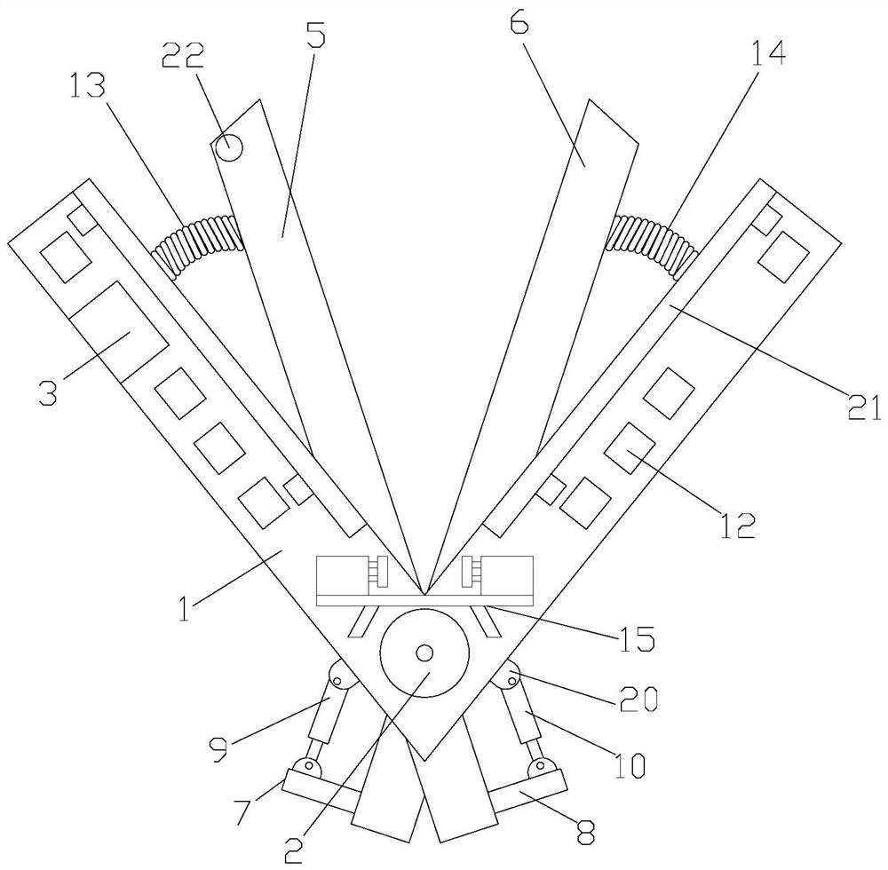
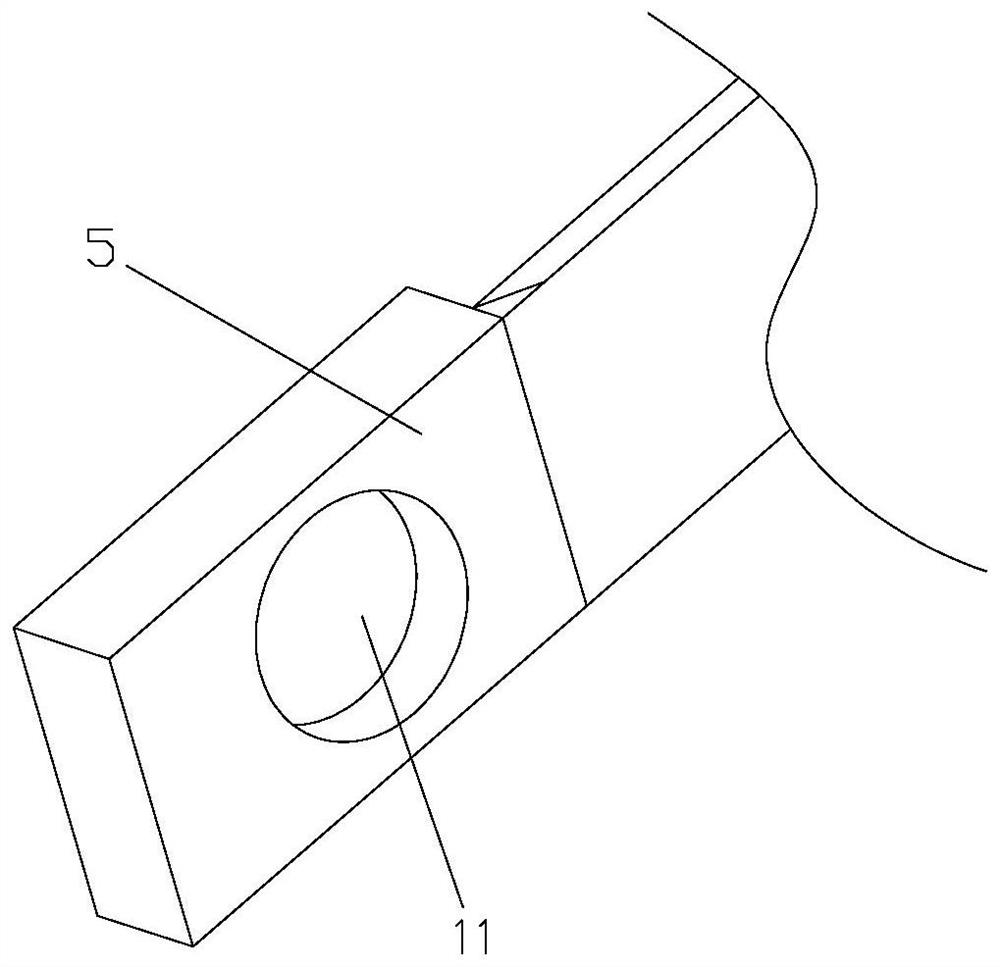
[0027] Such as Figure 1-4As shown, a plate shearing machine shearing mechanism includes a V-shaped support frame 1, a servo motor 2 and a control device 3, the V-shaped support frame 1 is provided with a perforation 4, and the V-shaped support frame 1 is provided with a The first blade 5 and the second blade 6, the ends of the first blade 5 and the second blade 6 pass through the perforation 4, the first blade 5 and the second blade 6 form an X-shaped setting, the first blade 5 and the end of the second blade 6 are respectively provided with a first connecting bar 7 and a second connecting bar 8, and a first electric cylinder 9 is arranged between the first connecting bar 7 and the V-shaped support frame 1, and the first electric cylinder 9 The two ends are respectively connected in rotation with the first connecting bar 7 and the V-shaped support frame 1, and a second electric cylinder 10 is arranged between the second connecting bar 8 and the V-shaped support frame 1, and t...

Embodiment 2

[0030] Such as Figure 1-4 As shown, a plate shearing machine shearing mechanism includes a V-shaped support frame 1, a servo motor 2 and a control device 3, the V-shaped support frame 1 is provided with a perforation 4, and the V-shaped support frame 1 is provided with a The first blade 5 and the second blade 6, the ends of the first blade 5 and the second blade 6 pass through the perforation 4, the first blade 5 and the second blade 6 form an X-shaped setting, the first blade 5 and the end of the second blade 6 are respectively provided with a first connecting bar 7 and a second connecting bar 8, and a first electric cylinder 9 is arranged between the first connecting bar 7 and the V-shaped support frame 1, and the first electric cylinder 9 The two ends are respectively connected in rotation with the first connecting bar 7 and the V-shaped support frame 1, and a second electric cylinder 10 is arranged between the second connecting bar 8 and the V-shaped support frame 1, and ...


PUM


Abstract

The invention discloses a shearing mechanism of a plate shearing machine, which comprises a V-shaped support frame, a servo motor and a control device. The V-shaped support frame is provided with a first blade and a second blade, and the first blade and the second blade are The ends all go through the perforation, the ends of the first blade and the second blade are respectively provided with a first connecting bar and a second connecting bar, and a first electric cylinder is arranged between the first connecting bar and the V-shaped support frame, so The two ends of the first electric cylinder are respectively rotatably connected to the first connecting bar and the V-shaped support frame, and a second electric cylinder is arranged between the second connecting bar and the V-shaped support frame, and both ends of the second electric cylinder are It is rotatably connected with the second connecting bar and the V-shaped support frame. The first and second installation holes are respectively provided with a first transmission mechanism and a second transmission mechanism. The servo motor, the first electric cylinder and the second The electric cylinders are electrically connected with the control device; the shearing mechanism of the shearing machine occupies less space laterally.

Description

technical field [0001] The invention relates to a shearing mechanism of a shearing machine. Background technique [0002] The shearing machine is a machine that uses one blade to make a reciprocating linear motion relative to the other blade to cut the plate. It uses the moving upper blade and the fixed lower blade to apply shearing force to metal sheets of various thicknesses with a reasonable blade gap, so that the sheets are broken and separated according to the required size. [0003] The shearing mechanism of the current shearing machine takes up relatively large space laterally. Therefore, those skilled in the art hope to develop a shearing mechanism that occupies less space laterally. Contents of the invention [0004] The technical problem to be solved by the present invention is to provide a shearing mechanism of a shearing machine which occupies less space in the lateral direction. [0005] In order to solve the above problems, the present invention adopts the ...

Claims


Application Information

Patent Timeline
Patent Type & Authority Patents(China)
IPC IPC(8): B23D17/00B23D17/02B23D35/00B23D33/00B23D33/02B23Q15/007
CPCB23D17/00B23D17/02B23D33/00B23D33/02B23D35/002B23Q15/007
Inventor 不公告发明人
Owner 江苏浩恩机床有限公司
Learn More