Efficient gas-solid separation and dust removal device

A technology of gas-solid separation and dust removal device, which is applied in the direction of combined device, separation method, and dispersed particle separation, etc., which can solve the problems of high dust removal pressure, heavy cleaning workload, and reduced suction efficiency in the second filter chamber, and achieve discharge Convenient and fast, good dust removal effect, simple structure

Pending Publication Date: 2020-05-01
CRCC HIGH TECH EQUIP CORP LTD
View PDF1 Cites 2 Cited by
  • Summary
  • Abstract
  • Description
  • Claims
  • Application Information

AI Technical Summary

Problems solved by technology

[0003] The Chinese utility model patent whose notification number is CN205220478U provides a storage hopper of a suction truck, which is composed of a settling chamber, a first filter chamber and a second filter chamber. Since the first filter chamber of the storage hopper is simple in structure, only There is a simple deflector used to change the airflow direction. The airflow speed remains unchanged before and after changing the airflow direction. It just uses simple inertia to remove dust. The dust removal effect is limited. A large amount of dust will directly enter the second filter chamber with the airflow, resulting in a second filter chamber. Filter chamber dust removal pressure is too high
In addition, when the material contains water, the mud spots formed by the droplets adsorbing dust are very easy to paste on the filter screen and block the filter screen. Due to the limited dust removal effect of the settling chamber and the first filter chamber, a large number of mud spots will directly enter the filter screen. The second filter chamber is pasted on the filter cartridge, resulting in increased wind resistance, increased system power loss, reduced suction efficiency, and even affected the normal use of the entire system, and the filter screen needs to be cleaned manually. The working environment is poor and the cleaning work large
In addition, when the storage hopper is unloading, it is necessary to turn the entire storage hopper around the turning shaft provided on one side of the storage hopper for tipping and unloading. Before unloading, the entire storage hopper cover must be opened and moved The location where the bucket is tilted and unloaded, the structure is complex

Method used


Image

  • Efficient gas-solid separation and dust removal device
  • Efficient gas-solid separation and dust removal device

Examples


Embodiment Construction

[0044]The following will clearly and completely describe the technical solutions in the embodiments of the present invention with reference to the accompanying drawings in the embodiments of the present invention. Obviously, the described embodiments are only some, not all, embodiments of the present invention. Based on the embodiments of the present invention, all other embodiments obtained by persons of ordinary skill in the art without making creative efforts belong to the protection scope of the present invention.

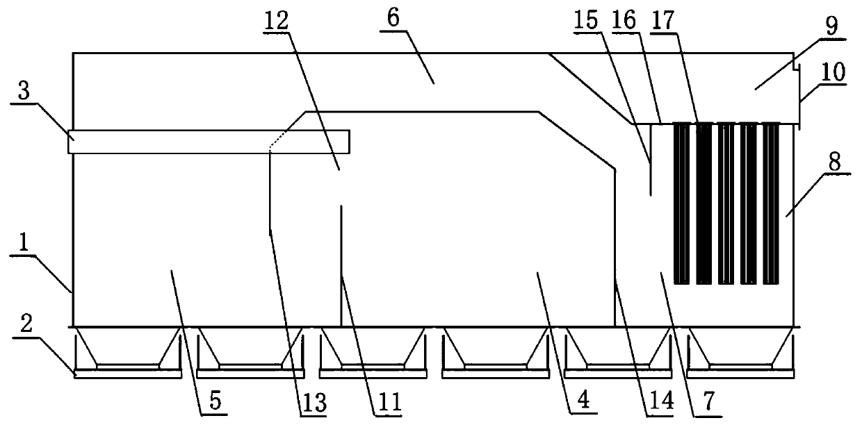
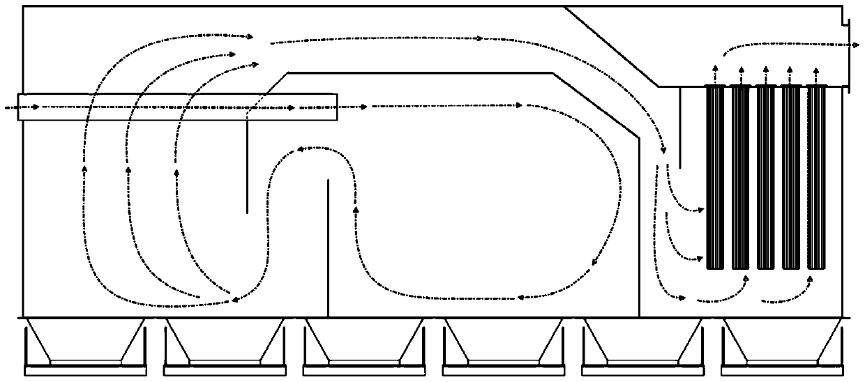
[0045] In order to overcome the problems existing in the gas-solid separation and dust removal equipment in the prior art, the embodiment of the present invention proposes a high-efficiency gas-solid separation and dust removal device, which can realize the separation of the material and the air in the two-phase fluid that is pneumatically conveyed , and filter the separated dusty gas to meet the discharge requirements and protect the gas source machinery.

[0...


PUM


Abstract

The invention relates to an efficient gas-solid separation and dust removal device. The internal space of a device main body (1) is sequentially divided into a 1# gravity settling chamber (4), a 2# gravity settling chamber (5) and a refined filtration chamber (7) through a first partition plate (11) and a second partition plate (14), which are arranged in the device main body (1); materials enterthe 1# gravity settling chamber (4); most of the materials settle for the first time in the 1# gravity settling chamber (4) under the action of self gravity; other fine materials enter the 2# gravitysettling chamber (5), the material settling direction in the 2# gravity settling chamber (5) is opposite to the airflow flowing direction, the fine materials are subjected to secondary settling in the2# gravity settling chamber (5), residual fine particles enter the refined filtration chamber (7) to be subjected to fine filtering treatment, finally, separation of the materials and gas is achieved, and clean air is exhausted. According to the device, materials and air in pneumatic conveying two-phase fluid can be separated, and separated dusty gas is filtered and dedusted, so that the purposesof meeting the emission requirement and protecting gas source machinery are achieved.

Description

technical field [0001] The invention relates to the technical field of gas-solid separation and dust removal, in particular to an efficient gas-solid separation and dust removal device. Background technique [0002] Pipeline material transportation is an important means of logistics, among which pneumatic transportation was first adopted by people, because pneumatic transportation has many obvious advantages over mechanical transportation: high transportation efficiency, overall simple equipment structure, convenient maintenance and management, and easy implementation Automation and environmental protection, etc., so it has developed rapidly in practical use and has become one of the ideal transportation methods. In recent years, it has been used in transportation, port handling, metallurgy, mining, electric power, chemical industry, casting, building materials, food , Textile and other industries are widely used. In addition, with the development and construction of the ci...

Claims


Application Information

Patent Timeline
Patent Type & Authority Applications(China)
IPC IPC(8): B01D45/02B01D45/08B01D46/12B01D50/00
CPCB01D45/02B01D45/08B01D46/12B01D50/20
Inventor 王深平孙荣民罗德昭王成
Owner CRCC HIGH TECH EQUIP CORP LTD
Why Eureka
Try Eureka