A low-profile planar helical antenna with a new feeding method

A planar spiral and low-profile technology, applied in the field of low-profile planar helical antennas, can solve the problems of insufficient bandwidth, small size, and insufficient gain of planar helical antennas, avoiding vertical impedance transformation modules, facilitating conformal installation, and feeding The effect of electricity is simple and firm

Active Publication Date: 2021-09-21
上海微波技术研究所(中国电子科技集团公司第五十研究所)
View PDF12 Cites 0 Cited by
  • Summary
  • Abstract
  • Description
  • Claims
  • Application Information

AI Technical Summary

Problems solved by technology

[0004] Patent document 107369904A (application number: 201710584031.X) discloses a low-profile high-gain ultra-wideband planar helical antenna to overcome the problems of insufficient bandwidth, insufficient gain and insufficient size of existing planar helical antennas; the invention includes Antenna radiator, back cavity, feed balun and feed connector. There is a metal hollow round platform in the back cavity. The metal hollow round platform is located on the dielectric bottom plate. The central axis coincides with the central axis of the back cavity. The vertical distance of the radiator satisfies the relational formula: λ is the working wavelength of the antenna radiator on the vertical projection of the position on the side surface to the corresponding position on the antenna radiator
[0005] In the above patents, the antenna impedance transformation and the feeding part are vertically connected to the antenna radiator, resulting in a large section size and complicated installation

Method used


Image

  • A low-profile planar helical antenna with a new feeding method
  • A low-profile planar helical antenna with a new feeding method
  • A low-profile planar helical antenna with a new feeding method

Examples


Embodiment Construction

[0031] The present invention will be described in detail below in conjunction with specific embodiments. The following examples will help those skilled in the art to further understand the present invention, but do not limit the present invention in any form. It should be noted that those skilled in the art can make several changes and improvements without departing from the concept of the present invention. These all belong to the protection scope of the present invention.

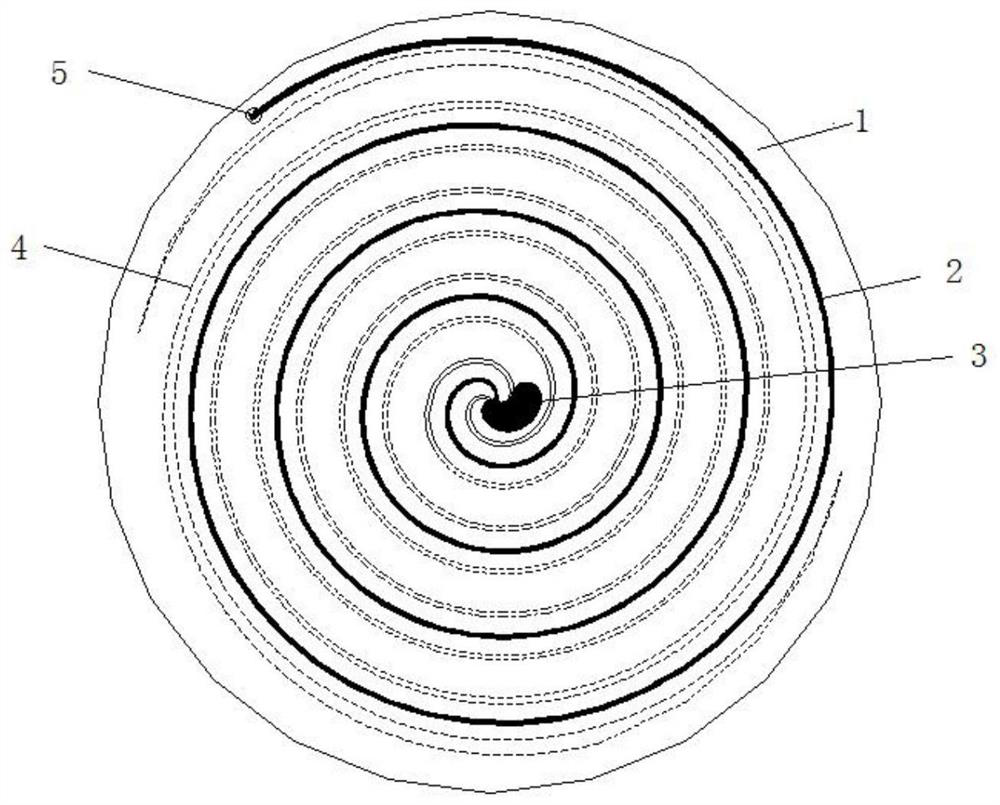
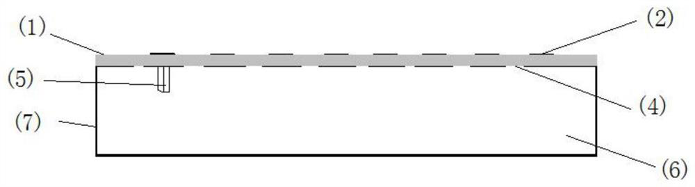
[0032] The low-profile planar helical antenna of the new feeding mode of the present invention is a planar helix antenna combined with double-sided helical arms, and the feeding of the double-sided helical arms and the end of the helical arm outside the dielectric plate is the key to ensure the transformation of antenna impedance. The antenna feeder is integrated into the design of the antenna helical arm, and has a simple structure, which avoids the complicated way of vertical feeding of the impedance t...


PUM


Abstract

The invention provides a low-profile planar helical antenna with a new feeding method, including: a double-sided dielectric plate, a front radiation unit, an aftermath absorption section, a rear radiation unit, coaxial feeding, a back cavity, and a side wall of the back cavity; The front spiral radiation unit is the antenna radiator on the front side of the double-sided dielectric board; the back spiral radiation unit is the antenna radiator on the back side of the double-sided dielectric board; Front; the coaxial feed is connected to the double-sided dielectric plate, the front radiation unit, and the rear radiation unit; the back cavity is a reflective back cavity located directly below the double-sided dielectric plate; the back cavity The side wall is the side wall of the back cavity, and is connected to the helical radiation unit at the back of the double-sided dielectric plate. The antenna of the technical solution of the present invention has a planar structure, which is convenient for conformal installation. Since the vertical impedance transformation module is avoided, the feeding of the antenna is simple and firm, and the cross-sectional size is small.

Description

technical field [0001] The invention relates to the field of antennas, in particular to a low-profile planar helical antenna with a new feeding method. Background technique [0002] Because the planar helical antenna has the characteristics of wide beam, wide frequency band and excellent circular polarization, it has a wide range of applications in military countermeasures and civil commercial fields, such as ultra-wideband radar detection systems, wireless communications, satellite communications and other fields. However, due to the traditional planar helical antenna feeding impedance transformation needs to be connected vertically to the antenna radiator, resulting in a large section size and complicated installation, while modern wireless communication, satellite communication and ultra-wideband detection radar systems have proposed light weight, low Therefore, how to simplify the antenna impedance transformation and feed structure and reduce the size of the antenna is a...

Claims


Application Information

Patent Timeline
Patent Type & Authority Patents(China)
IPC IPC(8): H01Q1/36H01Q1/38H01Q1/50H01Q5/25
CPCH01Q1/36H01Q1/38H01Q1/50H01Q5/25
Inventor 朱玉晓肖启荣孙鑫吴晓春
Owner 上海微波技术研究所(中国电子科技集团公司第五十研究所)
Why Eureka
Try Eureka