
Electromagnetic operating mechanism of circuit breaker

A technology of electromagnetic operation and electromagnetic mechanism, which is applied in the direction of protection switch operation/release mechanism, power device inside the switch, etc., and can solve problems such as difficult to meet reliability requirements, difficult to meet, and many faults

Pending Publication Date: 2020-04-28
WETOWN ELECTRIC GRP CO LTD
View PDF0 Cites 3 Cited by
  • Summary
  • Abstract
  • Description
  • Claims
  • Application Information

AI Technical Summary

Problems solved by technology

[0002] At present, all molded case reclosing switches in China are based on the traditional spring mechanism molded case switch, adding electric operation or motor drive mechanism for reclosing or opening. The spring mechanism is a multi-link mechanism with complex structure and failure. Many, slow opening and closing speed, poor reliability, and short life, it is difficult to meet the reliability requirements of the State Grid Corporation of China (the State Grid requires its mechanical life to be 5000-8000 times, and currently almost no manufacturers can meet this requirement requirements), and the action discreteness of tens of milliseconds
[0003] In addition, the high-reliability control and protection switch with an electromagnetic closing mechanism needs to be maintained by electromagnetic attraction for a long time, high energy consumption, and does not have a no-voltage short-circuit tripping protection mechanism, so it is difficult to meet GB14048.2 relevant standards in

Method used


Image

  • Electromagnetic operating mechanism of circuit breaker
  • Electromagnetic operating mechanism of circuit breaker
  • Electromagnetic operating mechanism of circuit breaker

Examples


Embodiment Construction

[0016] The electromagnetic operating mechanism of the circuit breaker of the present invention will be further described in detail below in conjunction with the accompanying drawings and specific embodiments.

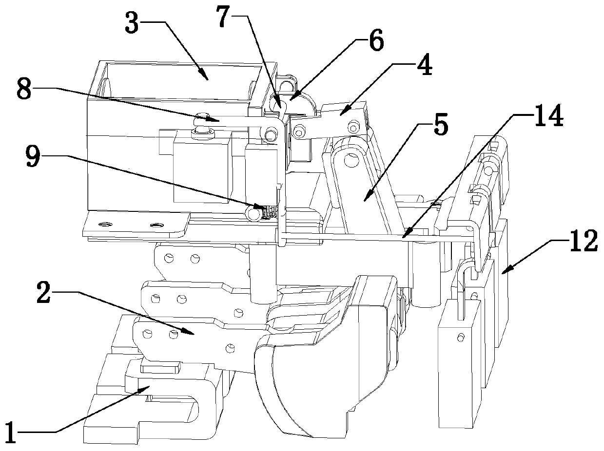
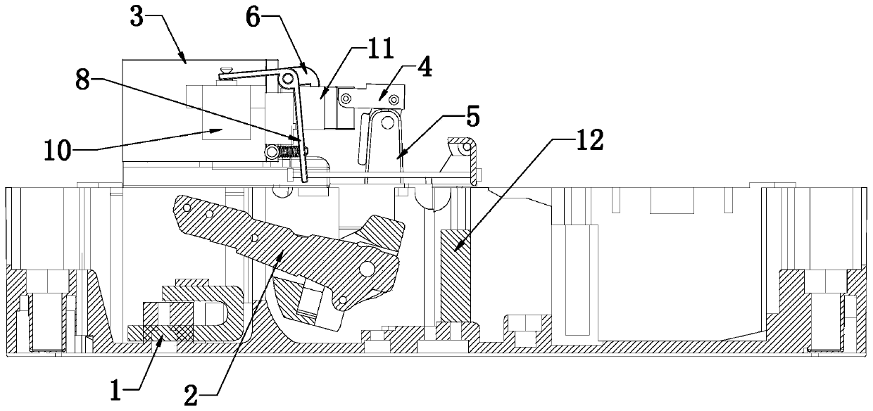
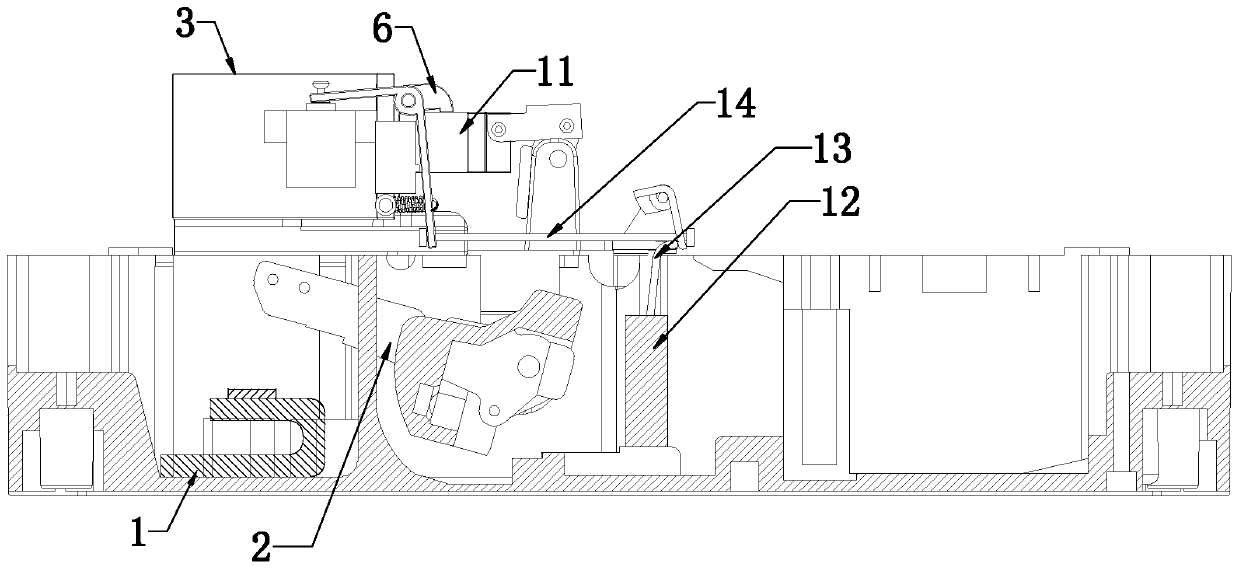
[0017] As shown in the figure, the circuit breaker electromagnetic operating mechanism of the present invention includes a static contact 1, a moving contact 2 cooperating with the static contact, and an electromagnetic mechanism 3 capable of operating the moving contact. The electromagnetic mechanism 3 includes The electromagnetic coil and the iron core matched with the electromagnetic coil, the front end of the iron core has a drive block, the iron core is hinged with a transition piece 4 through the drive block 11, and the transition piece 4 is hinged with a swing arm 5, that is to say, the transition connection Part 4 is hinged between the drive block 11 and the swing arm 5, and the end of the swing arm 5 is hinged with the moving contact 2 so as to drive the moving ...


PUM


Abstract

The invention discloses an electromagnetic operating mechanism of a circuit breaker. The electromagnetic operating mechanism comprises a static contact, a moving contact matched with the static contact, and an electromagnetic mechanism capable of operating the moving contact, wherein the electromagnetic mechanism is hinged with a swing arm through a transition connecting piece; the tail end of theswing arm is hinged to the moving contact so as to drive the moving contact to be opened and closed, a clamping hook used for being matched with the transition connecting piece is arranged on the front side of the electromagnetic mechanism, and the clamping hook can be driven by the elastic driving piece so as to be matched with the transition connecting piece to achieve closing locking or opening separation. With the adoption of the structure, the whole operating mechanism not only maintains the characteristics of no power consumption and no voltage short-circuit protection of the original spring mechanism in the closing state, but also has high reliability of the electromagnetic mechanism, overcomes all defects of the two mechanisms, has the best characteristics of the two mechanisms, can prolong the electrical life and the mechanical life by multiple times, and completely meets the technical standard requirements of the state grid for the high-reliability switch.

Description

technical field [0001] The invention relates to a switch mechanism for opening and closing in electrical equipment, in particular to an electromagnetic operating mechanism for a circuit breaker. Background technique [0002] At present, all molded case reclosing switches in China are based on the traditional spring mechanism molded case switch, adding electric operation or motor drive mechanism for reclosing or opening. The spring mechanism is a multi-link mechanism with complex structure and failure. Many, slow opening and closing speed, poor reliability, and short life, it is difficult to meet the reliability requirements of the State Grid Corporation of China (the State Grid requires its mechanical life to be 5000-8000 times, and currently almost no manufacturers can meet this requirement requirements), and the action discreteness of tens of milliseconds. [0003] In addition, the high-reliability control and protection switch with an electromagnetic closing mechanism ne...

Claims


Application Information

Patent Timeline
Patent Type & Authority Applications(China)
IPC IPC(8): H01H3/28H01H71/10
CPCH01H3/28H01H71/10
Inventor 季洪顺季家辉
Owner WETOWN ELECTRIC GRP CO LTD
Learn More