
Light source system and display device

A light source system and light splitting technology, applied in the field of optics, can solve problems such as loss, and achieve the effect of avoiding loss, avoiding uneven display, and wide color gamut

Active Publication Date: 2020-04-28
APPOTRONICS CORP LTD
View PDF7 Cites 4 Cited by
  • Summary
  • Abstract
  • Description
  • Claims
  • Application Information

AI Technical Summary

Problems solved by technology

Among them, the laser is focused on the regional diaphragm for reflection or transmission, and the fluorescence is only lost at the position of the regional coating
However, the larger the color gamut required by the projection system, the greater the proportion of red lasers in the light source. At the same time, the color coordinates of green fluorescent light can no longer meet the requirements of the color gamut standard, and a green laser module needs to be added

Method used


Image

  • Light source system and display device
  • Light source system and display device
  • Light source system and display device

Examples


Embodiment Construction

[0021] In the following description, a lot of specific details are set forth in order to fully understand the present invention, but the present invention can also be implemented in other ways different from those described here, and those skilled in the art can do it without departing from the meaning of the present invention. Similar applications, therefore, the present invention is not limited by the specific embodiments disclosed below. In the case of no conflict, the following embodiments and features in the embodiments can be combined with each other.

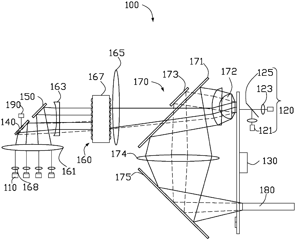
[0022] see figure 1 , figure 1 is a schematic structural view of the light source system 100 according to the first embodiment of the present invention. The light source system 100 can be applied to display devices, such as LCD, DLP, and LCOS projection display devices. It can be understood that the light source system 100 can also be used in a stage lighting system, a vehicle lighting system, an operation lighting sys...


PUM


Abstract

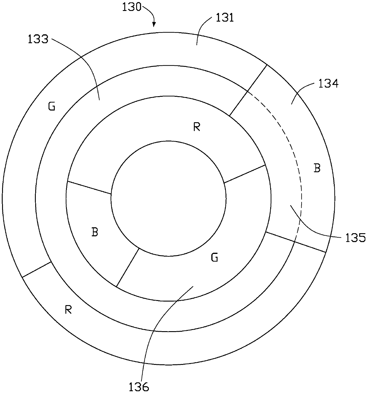
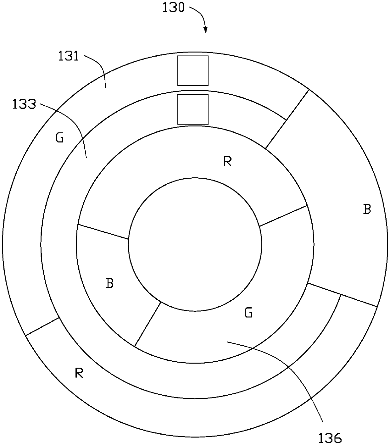
The invention provides a light source system. The light source system comprises an excitation light source used for emitting excitation light, a supplementary light source used for emitting supplementary light, a color wheel, a first reflecting device, a second reflecting device and a deflection device; the color wheel comprises a conversion region, a scattering region, a first reflection region and a second reflection region; the conversion region and the first reflection region are mutually connected to form a first circular ring; the scattering region and the second reflecting region are mutually connected to form a second circular ring; the second circular ring is arranged around the inner side or the outer side of the first circular ring; the position of the first reflection region isadjacent to the position of the second reflection region; the position of the conversion region is adjacent to the position of the scattering region; the conversion region is used for receiving the excitation light and emitting excited light; the scattering region is used for scattering and emitting the supplementary light; the first reflection region and the second reflection region are used forreflecting and emitting the exciting light; the first reflecting device and the second reflecting device are both used for reflecting the exciting light to the first circular ring; and the deflectiondevice is used for controlling the first reflecting device to deflect so as to irradiate the exciting light reflected by the first reflecting device to the second reflection region.

Description

technical field [0001] The invention relates to the field of optical technology, in particular to a light source system and a display device. Background technique [0002] At present, the projector market mainly includes bulb light source, LED light source, laser light source and laser-excited phosphor mixed light source. The laser-excited phosphor hybrid light source uses semiconductor lasers to excite different fluorescent pink segments on the color wheel to form different primary color lights. It has the advantages of high brightness, long life, high cost performance, and safe application, making it an ideal choice for projector light sources. [0003] Semiconductor red lasers and green lasers will produce speckle effect, which will affect the picture quality, and the efficiency of green laser is low, and the thermal stability of red laser is poor, which requires TEC to dissipate heat, which makes the surface of the laser easy to condense and dew, which affects the stabil...

Claims


Application Information

Patent Timeline
Patent Type & Authority Applications(China)
IPC IPC(8): G03B21/20G02B26/00
CPCG03B21/204G03B21/2066G02B26/008G02B26/00G03B21/20
Inventor 郭祖强鲁宁李屹
Owner APPOTRONICS CORP LTD
Learn More