


Quick Research
Generate reliable direction feasibility study reports for your R&D in just a few steps.

Technical Q&A
Discover and master advanced knowledge NOW. Basics, ideas, possibilities, all at once.

Find Solutions
As an expert in R&D theories, this can generate solutions to your technical problems instantly.

Evaluate Feasibility
Analyze your overall solution with one click, know your potential R&D risks in advance.

Monitor Landscape
Get weekly tech updates, stay abreast of the latest tech innovations and key insights.
Nondestructive testing method for open joint of track plate
A non-destructive testing, track slab technology, applied in measuring devices, using sonic/ultrasonic/infrasonic waves to analyze solids, and using sonic/ultrasonic/infrasonic waves for material analysis, etc. Achieve the effect of strong signal restoration ability, high sampling accuracy and strong filtering ability
- Summary
- Abstract
- Description
- Claims
- Application Information
AI Technical Summary
Problems solved by technology
Method used
Image


Examples
Embodiment 1
[0033] A non-destructive testing method for track slab separation, comprising the following steps:
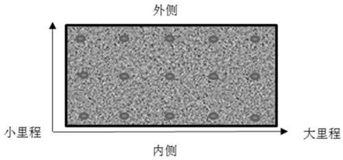
[0034] A. Preset or under the same working conditions on the project site, the track slab with a gap is used as a standard sample, and multiple measuring points are arranged at the position where the track slab has a gap, and the impact generated at the gap is received by knocking along the measuring point elastic wave signal.
[0035] B. Utilize spectrum analysis to extract the shock elastic wave signal tested in step A, and get the spectrum characteristic value according to the spectrum value of the shock elastic wave at each measuring point;
[0036] C. Arrange a number of measuring points on the track plate to be tested, and coordinate the measuring points, and receive the shock elastic wave signal generated by point-by-point tapping;
[0037] D. Use spectrum analysis to calculate the spectrum value of the test signal of the track plate, compare and analyze its spectrum va...
Embodiment 2
[0039] This embodiment is on the basis of embodiment 1:
[0040] In step D, if the spectrum value of the track slab test signal after spectrum analysis is greater than the characteristic value of the standard spectrum, it is judged that there is no gap in the track slab, and if it is smaller than the characteristic value of the spectrum, it is judged that the track slab has defects.
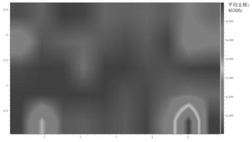
[0041] The planar imaging refers to displaying the comparison result of the spectrum value of the corresponding measuring point and the spectral feature value in the coordinate system through contrasting colors, and using a transitional color display between two adjacent measuring points. Transition colors are used to display between adjacent two measurements with different comparison results.
Embodiment 3
[0043] This embodiment is on the basis of embodiment 1:
[0044] The spectrum analysis uses the maximum entropy method.
[0045] The spectrum characteristic value of the B step is the average value of the spectrum values of the shock elastic wave at each measuring point.
[0046] When comparing the spectrum value of the track slab to be tested with the characteristic value of the spectrum, due to the differences in the structure of the track slab under different working conditions, such as the difference in thickness, position and angle of the track slab to be tested, the spectrum during comparison The value of the characteristic value will be adaptively adjusted according to the actual situation.
[0047] In step C, the distance between several measuring points should be 15-35cm.
[0048] Arrange the acceleration sensor on the measuring point, and tap the measuring point arranged on the surface of the track plate successively with a vibrating hammer or an automatic vibrat...
PUM
| Property | Measurement | Unit |
|---|---|---|
| diameter | aaaaa | aaaaa |
Abstract
Description
Claims
Application Information
 - R&D Engineer
- R&D Manager
- IP Professional
- Industry Leading Data Capabilities
- Powerful AI technology
- Patent DNA Extraction
Browse by: Latest US Patents, China's latest patents, Technical Efficacy Thesaurus, Application Domain, Technology Topic, Popular Technical Reports.
© 2024 PatSnap. All rights reserved.Legal|Privacy policy|Modern Slavery Act Transparency Statement|Sitemap|About US| Contact US: help@patsnap.com