A Control Calculation Method for the Propulsion System of Flexible Boom Tunneling Machine
A technology of propulsion system and calculation method, which is applied in the direction of earth drilling, mining equipment, tunnels, etc., can solve the problems of cumbersome process, less people, large errors, etc., achieve high promotion value, precise excavation, and improve control accuracy Effect
- Summary
- Abstract
- Description
- Claims
- Application Information
AI Technical Summary
Problems solved by technology
Method used
Image
Examples
Embodiment 1
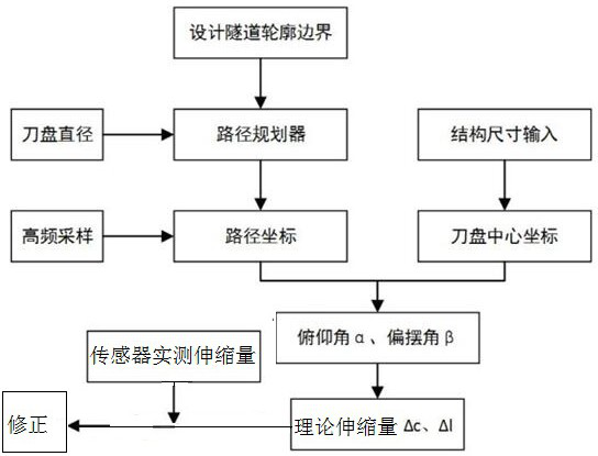
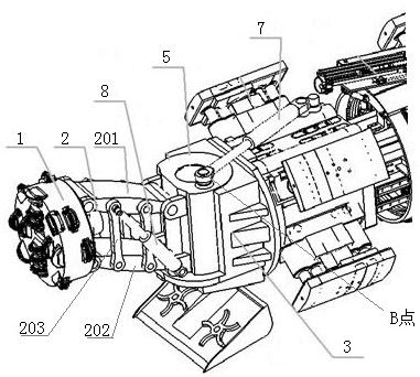
[0046] Embodiment 1, a control calculation method for the propulsion system of a flexible boom roadheader, the series swing arm is as follows figure 2 As shown, it includes a support base 3 and a swing arm 2. The support base 3 is rotated with a rotary shaft 5. The rotary shaft 5 is provided with an eccentric lug seat 6. The eccentric lug seat 6 is connected with a swing oil cylinder 7. One end of the swing oil cylinder 7 It is hinged with the eccentric lug seat 6, and the other end is connected with the main beam support system; the expansion and contraction of the swing oil cylinder drives the rotary shaft to rotate around its central axis, so as to realize the left and right swing of the swing telescopic arm in the vertical plane. The swing arm 2 includes an upper swing arm 201 and a lower swing arm 202 of equal length, the front ends of the upper swing arm 201 and the lower swing arm 202 are hinged with the cutter head 1, and the upper swing arm 201 is connected with the l...
Embodiment 2
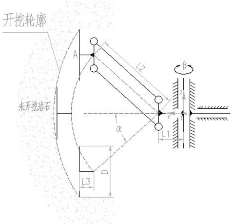
[0052] Embodiment 2, a control calculation method for the propulsion system of a flexible boom roadheader, the method for obtaining the rotation angle β and the swing angle α in step S2 is as follows:
[0053] S2.1: Take the axis of the rotary axis of the series swing arm as the Z axis to establish a coordinate system such as image 3 , 4 As shown, the y direction is perpendicular to the direction of the paper, and the origin O of the coordinate system is located on the upper end of the rotary axis. The coordinates of the center point A of the cutter head represent the position of the cutter head. The coordinates of A are obtained according to the geometric relationship. The coordinates of A can be expressed as:
[0054] A((L2cosα+L1+L3)cosβ, -(L2cosα+L1+L3)sinβ, L2sinα);
[0055] S2.2: Project the trajectory path coordinate data to the coordinate system yz plane. The yz plane is the same as the excavation cross section, which is convenient for calculating the actual cutterhe...
PUM
 Abstract
Description
Claims
Application Information
 - R&D Engineer
- R&D Manager
- IP Professional
- Industry Leading Data Capabilities
- Powerful AI technology
- Patent DNA Extraction
Browse by: Latest US Patents, China's latest patents, Technical Efficacy Thesaurus, Application Domain, Technology Topic, Popular Technical Reports.
© 2024 PatSnap. All rights reserved.Legal|Privacy policy|Modern Slavery Act Transparency Statement|Sitemap|About US| Contact US: help@patsnap.com


