An automatic casing type winder for hot melt adhesive film production

A hot-melt adhesive film and sleeve-type technology, which is applied in the direction of winding strips, thin material handling, transportation and packaging, etc., can solve the problems of cumbersome operation of hot-melt adhesive films, and achieve the effect of avoiding slipping and improving efficiency

Active Publication Date: 2021-05-11
安徽垣锽新材料科技有限公司
View PDF5 Cites 2 Cited by
  • Summary
  • Abstract
  • Description
  • Claims
  • Application Information

AI Technical Summary

Problems solved by technology

[0005] In order to overcome the cumbersome shortcomings of manually inserting the rewinding paper roll and taking out the completed hot melt adhesive film before rewinding, the technical problem of the present invention is to provide a method that can automatically complete the rewinding, A winding machine for hot melt adhesive film production that can automatically sleeve and conveniently take out the rolled hot melt adhesive film

Method used


Image

  • An automatic casing type winder for hot melt adhesive film production
  • An automatic casing type winder for hot melt adhesive film production
  • An automatic casing type winder for hot melt adhesive film production

Examples


Embodiment 1

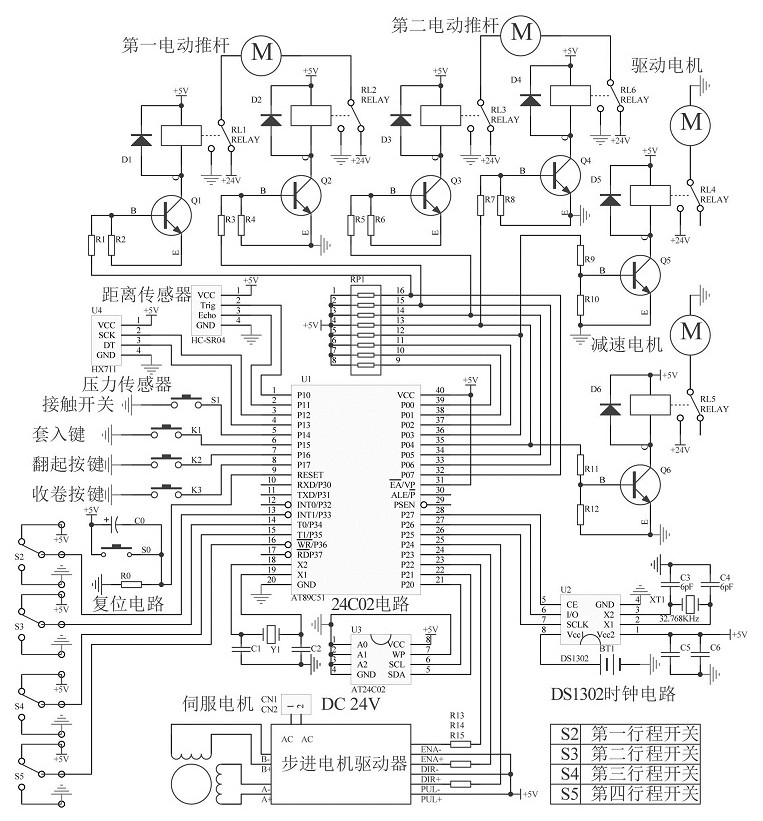
[0024] An automatic casing type winder for hot melt adhesive film production, such as Figure 1-2 As shown, it includes an organic base 1, a vertical bar 2, a fixed frame 3, a support mechanism 5 and a rotating mechanism 6, a vertical bar 2 is installed on the left side of the top of the machine base 1, a support mechanism 5 is installed on the right side of the top of the machine base 1, and the vertical bar 2 The top is connected with a fixed frame 3, and a rotating mechanism 6 is arranged between the bottom of the vertical bar 2 and the right wall of the fixed frame 3.

[0025] The support mechanism 5 includes a first electric push rod 51, a pressure sensor 52, a placement plate 53, an extension rod 54, a distance sensor 55, a second electric push rod 56, an L-shaped plate 57 and a contact switch 58, and the right side of the top of the machine base 1 A first electric push rod 51 and a second electric push rod 56 are installed, the second electric push rod 56 is positioned ...

Embodiment 2

[0032] On the basis of Example 1, such as Figure 1-7 As shown, it also includes a blanking mechanism 7, and the blanking mechanism 7 includes a protective plate 71, a servo motor 72, a drum 73, a synchronous belt 74, a third stroke switch 75, a fourth stroke switch 76, a guide sleeve 77, and a connecting plate 78, placing frame 79, sliding sleeve 710, sliding bar 711, elastic cord 712, push plate 713 and inserting key 714, two guide sleeves 77 are set on the vertical bar 2 top, and two guide sleeves 77 right sides are provided with Place the frame 79, the left end of the base 1 is provided with a protective plate 71, the left side of the top of the base 1 is equipped with a servo motor 72, the output shaft of the servo motor 72 and the left side of the top of the fixed frame 3 are provided with a roller 73, and the upper side of the roller 73 It is connected with the left side of the top of the fixed frame 3 in a rotational manner, and a timing belt 74 is wound between the ro...


PUM


Abstract

The invention relates to a winding machine for hot-melt adhesive film production, in particular to an automatic casing-type winding machine for hot-melt adhesive film production. The technical problem of the present invention is how to provide a hot-melt adhesive film production winder that can automatically complete the winding, can automatically sleeve and conveniently take out the hot-melt adhesive film that has been rolled. An automatic sleeve-type winding machine for hot melt adhesive film production, including a machine base, a vertical rod, etc.; the vertical rod is installed on the left side of the top of the machine base. Through the cooperation of the supporting mechanism and the rotating mechanism, the present invention can complete the automatic winding of the hot-melt adhesive film and facilitate the user to take out the rolled-up hot-melt adhesive film, and the unloading mechanism can complete the automatic insertion into the winding paper roll to complete Rewinding improves the efficiency of rewinding the hot-melt adhesive film, and the set limit plate can limit the inserted rewinding paper tube to prevent the rewinding paper tube from sliding during the rewinding process.

Description

technical field [0001] The invention relates to a winding machine for hot-melt adhesive film production, in particular to an automatic casing-type winding machine for hot-melt adhesive film production. Background technique [0002] Hot melt adhesive film is a film product with or without release paper, which can be conveniently operated continuously or intermittently. It can be widely used in all kinds of fabrics, papers, polymer materials and metal bonding. [0003] During the production process of hot melt adhesive film, it is necessary to roll and store the produced hot melt adhesive film. However, the operation mode of most winding machines at present is that it needs to be manually inserted into the winding paper roll before winding. , and then carry out the winding operation. After the winding is completed, the removal method is relatively cumbersome, and the hot melt adhesive film that has been rolled needs to be manually supported, which consumes a lot of manpower a...

Claims


Application Information

Patent Timeline
Patent Type & Authority Patents(China)
IPC IPC(8): B65H19/30B65H26/08
CPCB65H19/30B65H26/08B65H2301/418B65H2701/1133
Inventor 吴光祥
Owner 安徽垣锽新材料科技有限公司
Why Eureka
Try Eureka