Zone-limiting welding power supply

A welding power source and position-limiting technology, applied in welding equipment, auxiliary welding equipment, welding/cutting auxiliary equipment, etc., can solve the problems of increasing the difficulty of maintenance of subsequent devices, the influence of the work of adjacent devices, and the weakening of the internal cooling effect. , to ensure positioning stability and application security, reduce support strength requirements, ensure the quality of operation and the effect of operation

Pending Publication Date: 2020-04-28
昆山博尔勒自动化科技有限公司
View PDF0 Cites 0 Cited by
  • Summary
  • Abstract
  • Description
  • Claims
  • Application Information

AI Technical Summary

Problems solved by technology

However, the interior of the device is generally set with a unified chamber structure, which leads to the comparison of the installation of internal devices according to their own volume and the size of the reserved space, which reduces the order of the device and increases the difficulty of maintenance of subsequent device devices. At the same time, it is easy to It produces the working influence of adjacent devices, reduces the service life, and also weakens the internal cooling effect, which is not conducive to the long-term welding operation

Method used


Image

  • Zone-limiting welding power supply
  • Zone-limiting welding power supply
  • Zone-limiting welding power supply

Examples


Embodiment Construction

[0029] The present invention will be further described below in conjunction with the accompanying drawings and specific embodiments.

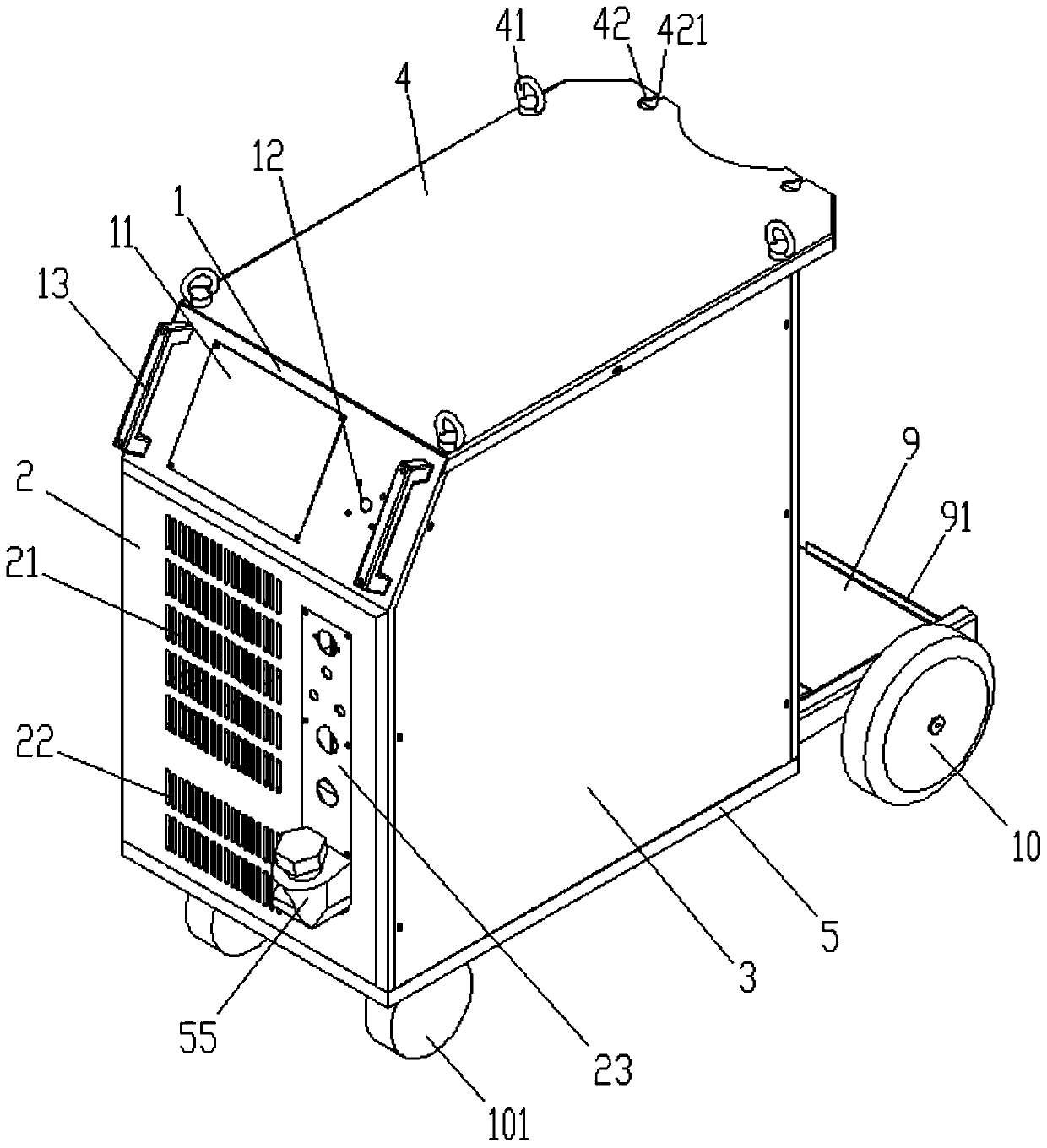
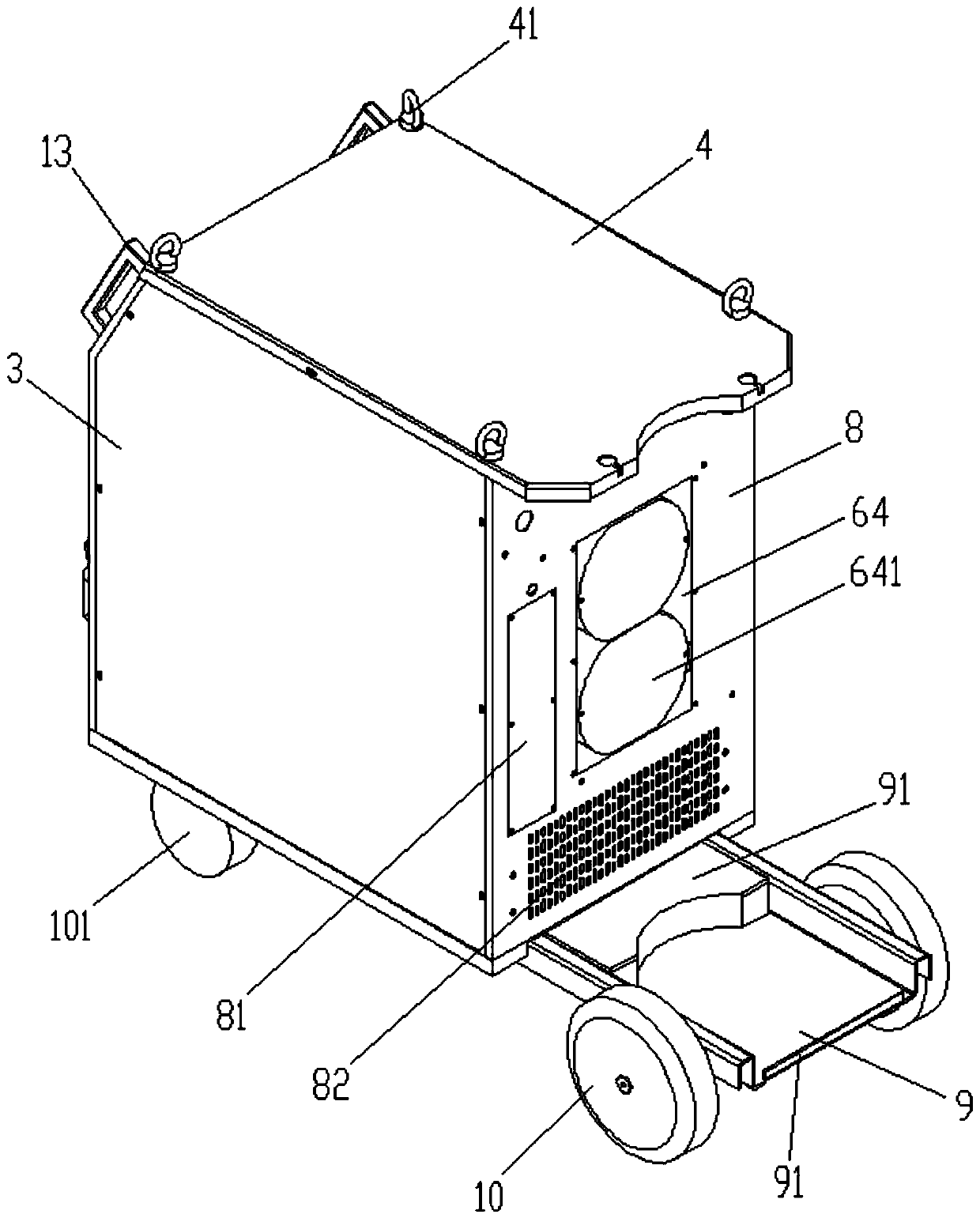
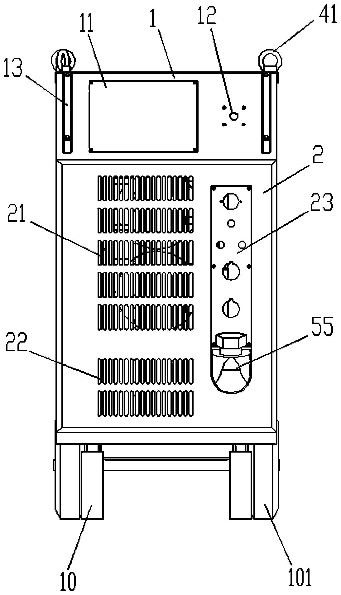
[0030] Such as figure 1As shown above, the welding power source is surrounded by the front plate, side plate 3, rear plate 8, top plate 4 and welding bottom plate 5, and the gas cylinder fixing position is set behind the welding bottom plate 5 and the rear plate , so as to realize the placement of the back-type gas cylinder, ensure the stability of the positioning and the effect of the device.

[0031] The welded bottom plate 5 can be set as a rectangular plate with a width less than 477mm according to the application environment, so as to meet the passing diameter of a standard door and ensure the displacement quality of the device. At this time, as shown in the figure, the front plate, the side plates 3 and the rear plate 8 are vertically connected to the four ends of the welded bottom plate 5 and realize the screw fastening connection of th...


PUM

PropertyMeasurementUnit
Diameter sizeaaaaaaaaaa

Abstract

The invention discloses a zone-limiting welding power supply applied to the welding field. The zone-limiting welding power supply comprises a content chamber, a gas cylinder fixing position and a driving wheel, wherein the content chamber is enclosed by a front plate, side plates, a back plate, a top plate and a welding bottom plate; the gas cylinder fixing position is positioned on an outer sideof the content chamber; the inside of the content chamber is partitioned into a first chamber, a second chamber and a third chamber which are not in communication with one another in an axial direction toward the top plate by a core support plate and a top layer partition plate which are arranged in sequence in parallel to the direction of the welding bottom plate; the front plate, the back plateand the welding bottom plate are provided with heat dissipation holes respectively; the gas cylinder fixing position is arranged on an end part of the back plate on which the welding bottom plate is arranged; and the top plate is provided with a plurality of flying rings. Through the adoption of the welding power supply, an internal space and an external functional area are partitioned, so that the clarity of the configuration structure is improved, and the internal space utilization rate and the structural working quality is enhanced. At the same time, the driving wheel and the flying rings are used cooperatively, so that the displacement requirements in different environments can be met; the functional implementation of the device is ensured; and the application range of the device is enlarged.

Description

technical field [0001] The invention relates to a zone-limited welding power supply used in the welding field. Background technique [0002] In recent years, the development of aerospace, transportation, marine engineering and other industries has greatly promoted the progress of welding technology. With the variety of products, materials and conditions of use, the requirements for welding quality are getting higher and higher. Therefore, how to use high-quality and efficient welding technology to meet the current needs is a task facing welding workers. Improving welding production efficiency and welding quality, realizing welding automation production, and reducing welding defects have become urgent requirements for actual production. The configuration of high-quality welding power source plays a vital role in the regulation of welding quality. On the one hand, the welding power supply needs to adjust the welding parameters through the built-in chip, on the other hand, it...

Claims


Application Information

Patent Timeline
IPC IPC(8): B23K37/00
CPCB23K37/00
Inventor 李波杨龙
Owner 昆山博尔勒自动化科技有限公司
Why Eureka
Try Eureka