
Escape preventing device of insect trap

An insect trap and anti-escape technology, applied in the field of insect traps, can solve the problems of single insect trap, incompleteness, waste of manpower and material resources, etc., and achieve the effects of improving insect trapping efficiency, increasing practicability and ensuring space.

Inactive Publication Date: 2020-04-28
湖南天长农业科技发展有限公司
View PDF11 Cites 2 Cited by
  • Summary
  • Abstract
  • Description
  • Claims
  • Application Information

AI Technical Summary

Problems solved by technology

[0002] Insect trap is a device that people want to increase the production of animals and plants. Due to the wide variety of pests, sometimes it is necessary to target a certain pest, so various insect traps have been developed to deal with pests. Want to To reduce pests, it is necessary to understand the habits of pests, such as phototaxis, the use of sex pheromones to lure pests, and food lures to lure pests to designated locations, then use insect traps to collect them, and then use electric shocks or various reagents to reduce pests , which will reduce the damage of insect pests to crops, reduce the impact of insect pests, and increase the yield of animals and plants, but the existing insect traps are sometimes not convenient enough, and sometimes require manual assistance, which wastes manpower and material resources, and pests enter It is possible to crawl out of the insect collection bottle, such an insect trap is not perfect, and it will also lead to poor efficiency of insect trap, and the insect trap is too simple, combining it with other devices can not only realize the function of insect trap , but also to ensure aesthetics, but also to improve functionality

Method used


Image

  • Escape preventing device of insect trap
  • Escape preventing device of insect trap
  • Escape preventing device of insect trap

Examples


Embodiment Construction

[0019] The following will clearly and completely describe the technical solutions in the embodiments of the present invention with reference to the accompanying drawings in the embodiments of the present invention. Obviously, the described embodiments are only some, not all, embodiments of the present invention. Based on the embodiments of the present invention, all other embodiments obtained by persons of ordinary skill in the art without making creative efforts belong to the protection scope of the present invention.

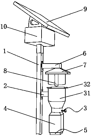
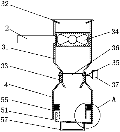
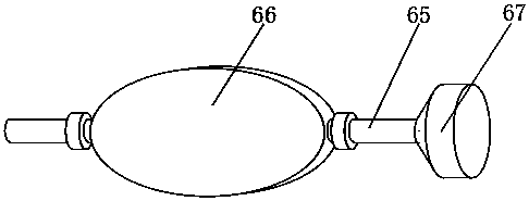
[0020] see Figure 1-4 , the present invention provides a technical solution: an anti-escape device for an insect trap, comprising an insect trap main body 1, a connecting rod 2, an anti-escape assembly 3, an insect collecting bottle 4, an insect pouring assembly 5, a lamp arm 6, a lampshade 7, and an electric lamp 8. The solar panel 9 and the storage battery 10 are connected with a connecting rod 2 by bolts on one side of the central outer wall of the insect ...


PUM


Abstract

The invention discloses an escape preventing device of an insect trap. The escape preventing device of the insect trap includes an insect trap body, a connecting rod, an escape preventing component, an insect collection bottle, an insect pouring component, a lamp arm, a lamp cover, an electric lamp, a solar panel and a storage battery, wherein the connecting rod is connected to the outer wall of the middle of one side of the insect trap body through a bolt, the escape preventing component is fixed to the outer wall of an opposite side of the connecting rod, and the outer wall of the bottom ofa funnel is inserted into the insect collection bottle; and the insect pouring component is fixed to the inner wall of the bottom of the insect collection bottle. Pests are lured through the phototaxis of pests, not only can trapping of the pests be ensured, but also light can be provided so as to increase practicality; then, the pests are collected into the insect collection bottle through an induced draft fan, and the pests cannot get out of the insect collection bottle through the special funnel and a wind pressure valve, so that the efficiency of insect trapping is improved; and the pestscan be poured out by staff at intervals, so that space in the insect collection bottle is ensured.

Description

technical field [0001] The invention relates to the technical field of insect traps, in particular to an anti-escape device for insect traps. Background technique [0002] Insect trap is a device that people want to increase the production of animals and plants. Due to the wide variety of pests, sometimes it is necessary to target a certain pest, so various insect traps have been developed to deal with pests. Want to To reduce pests, it is necessary to understand the habits of pests, such as phototaxis, the use of sex pheromones to lure pests, and food lures to lure pests to designated locations, then use insect traps to collect them, and then use electric shocks or various reagents to reduce pests , which will reduce the damage of insect pests to crops, reduce the impact of insect pests, and increase the yield of animals and plants, but the existing insect traps are sometimes not convenient enough, and sometimes require manual assistance, which wastes manpower and material ...

Claims


Application Information

Patent Timeline
Patent Type & Authority Applications(China)
IPC IPC(8): A01M1/08F21S9/03F21V33/00
CPCA01M1/08F21S9/035F21V33/00
Inventor 李华平
Owner 湖南天长农业科技发展有限公司
Learn More