Eureka AIR delivers breakthrough ideas for toughest innovation challenges, trusted by R&D personnel around the world.

Retracting mechanism of a retractable lens

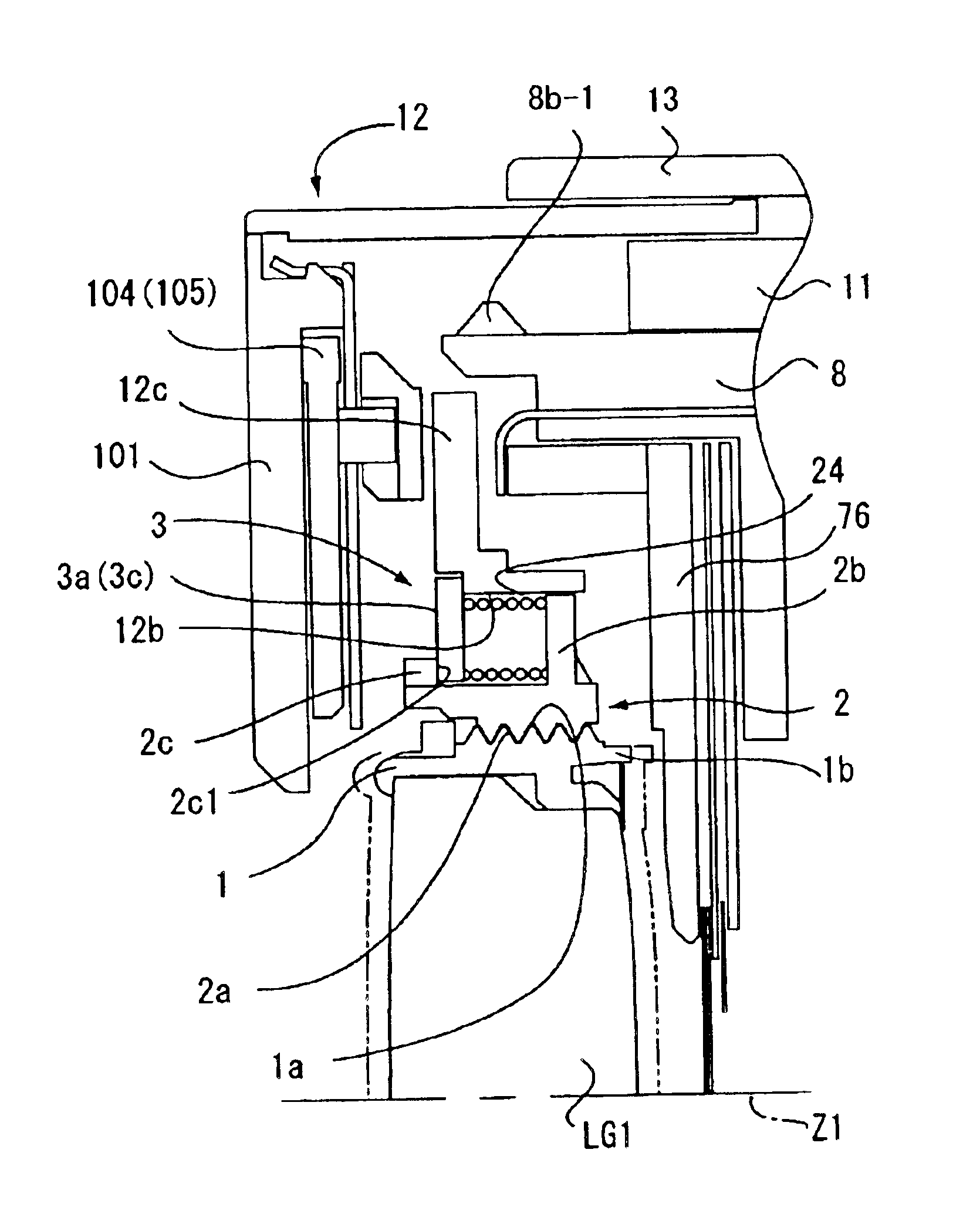
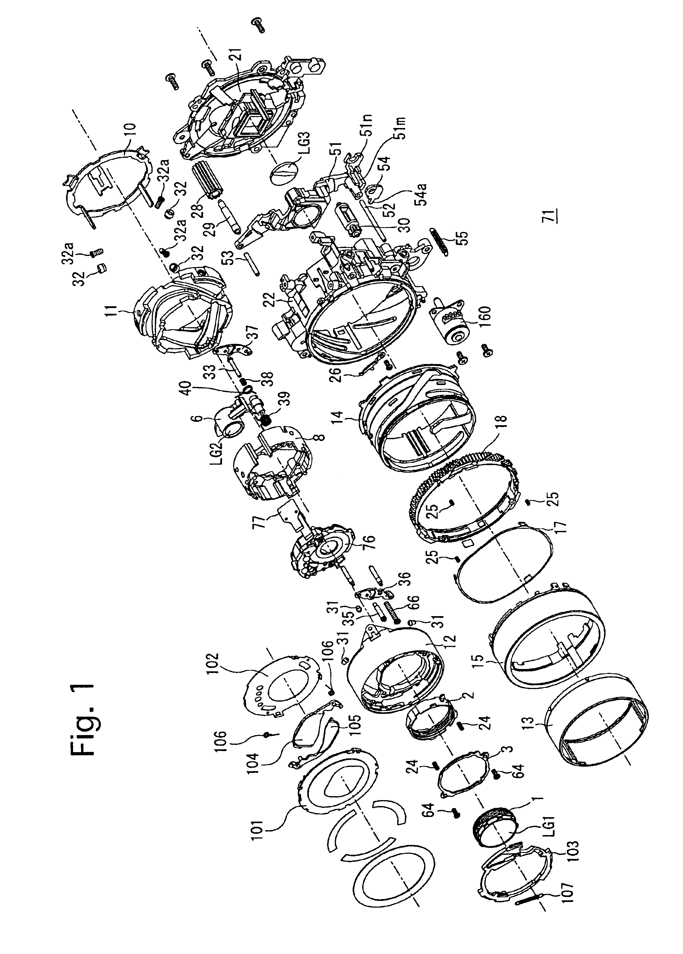
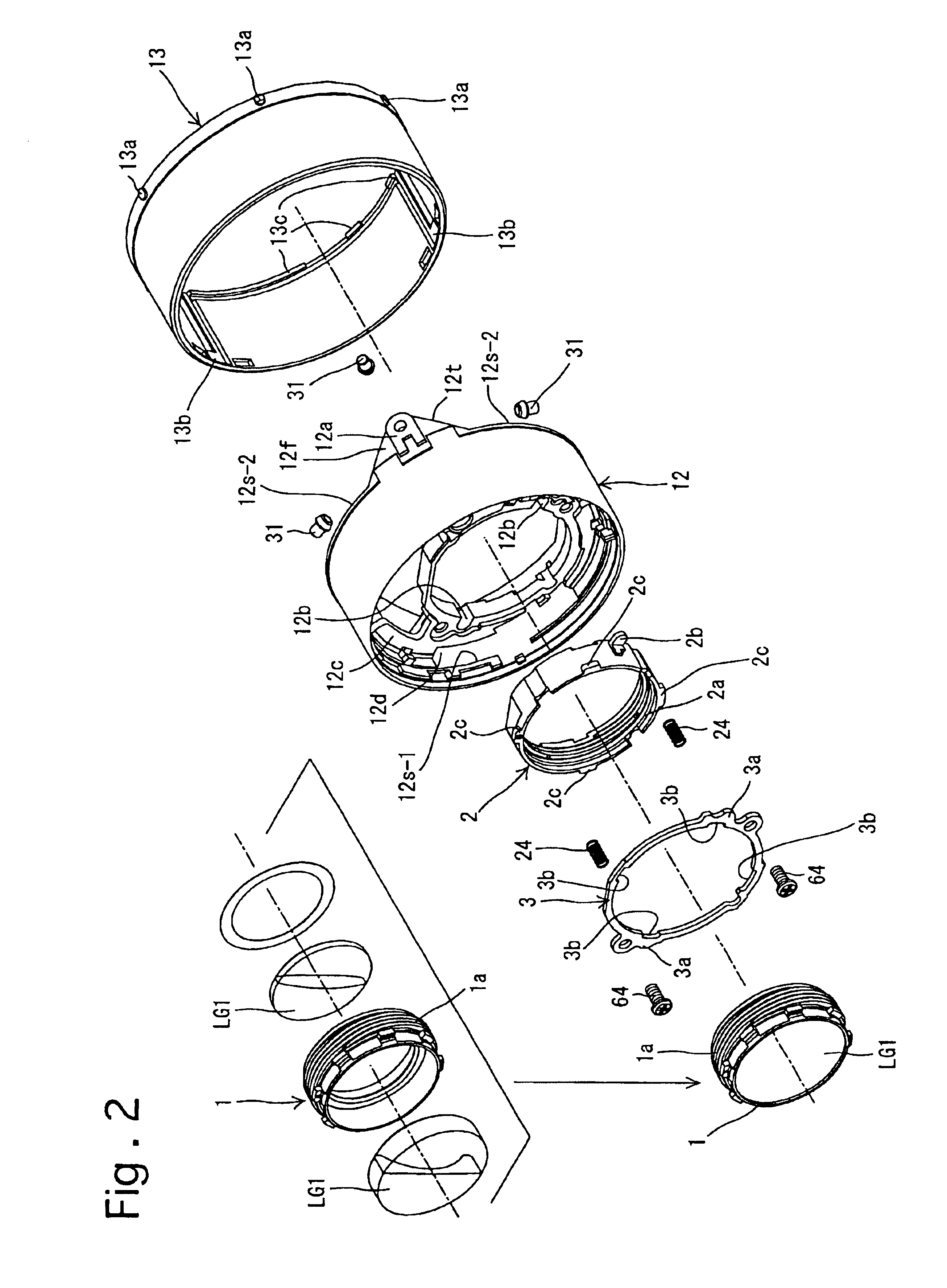
a retractable lens and mechanism technology, applied in the field of retractable lenses, can solve the problems of difficult to reduce the length of the zoom lens to a minimum, and achieve the effect of reducing the length of the retractable lens

Inactive Publication Date: 2006-04-11
ASAHI KOGAKU KOGYO KK
View PDF99 Cites 23 Cited by
  • Summary
  • Abstract
  • Description
  • Claims
  • Application Information

AI Technical Summary

Benefits of technology

"The present invention provides a retracting mechanism for a retractable lens that reduces the length of the lens in its fully retracted state while still allowing for adjustment of the position-adjustable lens group in its operating state. The mechanism includes an external barrel, adjustment ring, lens frame, fixing ring, spring, and engagement projections. The adjustment ring is positioned in the external barrel and can move forward and rearward without rotating. The lens frame is screwed into the adjustment ring and can be fixed in place using the fixing ring. The mechanism also includes a stopper to prevent excessive movement of the adjustment ring. The lens group can move along the optical axis to perform focal-length varying and focusing operations. Overall, the mechanism allows for a compact and adjustable retractable lens."

Problems solved by technology

However, according to this structure, since sufficient space allowing the position-adjustable lens group (the lens frame) to move forward and rearward for adjustment relative to the external barrel must be secured, such a space makes it difficult to reduce the length of the zoom lens to a minimum when the zoom lens is fully retracted.

Method used


Image

  • Retracting mechanism of a retractable lens
  • Retracting mechanism of a retractable lens
  • Retracting mechanism of a retractable lens

Examples


Embodiment Construction

[0181]In some of the drawings, lines of different thicknesses and / or different types of lines are used as the outlines of different elements for the purpose of illustration. Additionally, in some cross sectional drawings, several elements are shown on a common plane, though positioned in different circumferential positions, for the purpose of illustration.

[0182]In FIG. 22, the symbols “(S)”, “(L)”, “(R)” and “(RL)” which are each appended as a suffix to the reference numeral of some elements of a present embodiment of a zoom lens (zoom lens barrel) 71 (see FIGS. 5 through 10) indicate that the element is stationary, the element is solely movable linearly along a lens barrel axis Z0 (see FIGS. 9 and 10) without rotating about the lens barrel axis Z0, the element is rotatable about the lens barrel axis Z0 without moving along the lens barrel axis Z0, and the element is solely movable along the lens barrel axis Z0 while rotating about the lens barrel axis Z0, respectively. Additionally...


PUM


Abstract

A retracting mechanism of a retractable lens includes an external barrel movable in an optical axis direction, an adjustment ring positioned in said external barrel and configured to be guided linearly in the optical axis direction without rotating, a stopper configured to set a rear movement limit of said adjustment ring with respect to said external barrel, a lens frame configured to hold a lens group, said lens frame configured to be screwed into said adjustment ring, a fixing ring fixed to said external barrel and configured to prevent said adjustment ring coming off said external barrel, and at least one spring positioned between said fixing ring and said adjustment ring and configured to bias said adjustment ring toward the rear movement limit of said adjustment ring with respect to said external barrel.

Description

BACKGROUND OF THE INVENTION[0001]1. Field of the Invention[0002]The present invention relates to a retractable lens (retractable lens barrel) which is retracted to reduce the length thereof when not in use, e.g., a retractable photographing (imaging) lens which is retracted into a camera body upon power being turned OFF.[0003]2. Description of the Related Art[0004]In a conventional zoom lens disclosed in Japanese Unexamined Patent Publications Nos. 10-161001 and 11-231201, if a lens group (position-adjustable lens group), an axial position of which is to be adjustable relative to a lens barrel, a lens frame which holds the position-adjustable lens group is screwed into an external barrel, the axial position of the position-adjustable lens group can be adjusted by rotating the lens frame relative to the external barrel.[0005]However, according to this structure, since sufficient space allowing the position-adjustable lens group (the lens frame) to move forward and rearward for adjust...

Claims


Application Information

Patent Timeline
Patent Type & Authority Patents(United States)
IPC IPC(8): G03B17/04G02B7/00G02B7/02G02B7/08G02B7/10G02B15/14
CPCG02B7/022G02B7/026G02B15/14G02B7/102G02B7/08G02B15/143G02B7/04G03B2217/00
Inventor NOMURA, HIROSHI
Owner ASAHI KOGAKU KOGYO KK
Why Eureka
Eureka Blog
Learn More