Optical systems, metrology apparatus and associated methods

An optical system and measurement technology, applied in the field of optical systems, can solve problems such as insufficient resolution

Pending Publication Date: 2020-04-24
ASML NETHERLANDS BV
View PDF27 Cites 0 Cited by
  • Summary
  • Abstract
  • Description
  • Claims
  • Application Information

AI Technical Summary

Problems solved by technology

Today, many forms of optical metrology are known, and as critical dimensions in manuf...

Method used


Image

  • Optical systems, metrology apparatus and associated methods
  • Optical systems, metrology apparatus and associated methods
  • Optical systems, metrology apparatus and associated methods

Examples


Embodiment Construction

[0132] In this document, the terms "radiation" and "beam" are used to cover all types of electromagnetic radiation, including ultraviolet radiation (for example, having a wavelength of 365nm, 248nm, 193nm, 157nm or wavelength in the range of about 5nm-100nm).

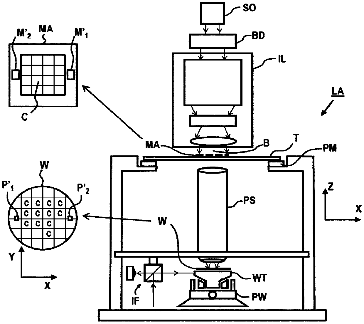
[0133] As used herein, the terms "reticle," "mask," or "patterning device" may be broadly interpreted to refer to a general patterning device that can be used to impart a patterned cross-section to an incident radiation beam, the pattern The normalized cross-section corresponds to the pattern to be created in the target portion of the substrate. In this context, the term "light valve" may also be used. Examples of other such patterning devices include programmable reflector arrays and programmable LCD arrays, in addition to classical masks (transmissive or reflective, binary, phase-shifted, hybrid, etc.).

[0134] figure 1 A lithographic apparatus LA is schematically depicted. The lithographic apparatus LA comprise...


PUM


Abstract

An optical system (OS) for focusing a beam of radiation (B) on a region of interest in a metrology apparatus is described. The beam of radiation (B) comprises radiation in a soft X-ray or Extreme Ultraviolet spectral range. The optical system (OS) comprises a first stage (S1) for focusing the beam of radiation at an intermediate focus region. The optical system (OS) comprises a second stage (S2) for focusing the beam of radiation from the intermediate focus region onto the region of interest. The first and second stages each comprise a Kirkpatrick-Baez reflector combination. At least one reflector comprises an aberration- correcting reflector.

Description

[0001] Cross References to Related Applications [0002] This application claims priority to European (EP) application 17188979.3 filed on September 1, 2017 and European (EP) application 18172804.9 filed on May 17, 2018, the entire contents of which are incorporated herein by reference. technical field [0003] The present invention relates to optical systems and associated methods for use in, but not limited to, metrology devices. Background technique [0004] A lithographic apparatus is a machine configured to apply a desired pattern to a substrate. A lithographic apparatus may be used, for example, in the manufacture of integrated circuits (ICs). A lithographic apparatus may project a pattern (also commonly referred to as a "design layout" or "design") onto radiation-sensitive material provided on a substrate (e.g., a wafer), for example at a patterning device (e.g., a mask) (resist) layer. [0005] To project a pattern on a substrate, a lithographic apparatus may use...

Claims


Application Information

Patent Timeline
IPC IPC(8): G21K1/06G03F7/00G03F7/20G02B17/04
CPCG02B17/04G21K1/067G21K7/00G21K2201/064G21K2201/067G01N21/4788G01N21/9501G03F7/2008G03F7/2039G03F7/70033G03F7/70158G03F7/70641G21K1/062
Inventor S·T·范德波斯特S·M·B·鲍默P·D·范福尔斯特T·W·图克F·兹杰普H-K·尼恩海斯J·M·A·范登埃厄伦比埃姆德
Owner ASML NETHERLANDS BV
Why Eureka
Try Eureka