Pipe device having a bonded joint

A technology that combines connection and pipe fittings, applied in the direction of hose connection devices, pipes/pipe joints/fittings, pipe connection arrangements, etc., can solve problems such as leakage, small torque, etc., and achieve low leakage rate, increased area, and high tensile strength Effect

Active Publication Date: 2020-04-24
NORMA GERMANY GMBH
View PDF14 Cites 0 Cited by
  • Summary
  • Abstract
  • Description
  • Claims
  • Application Information

AI Technical Summary

Problems solved by technology

[0004] The disadvantage of this construction is that the connection between the pipe and the connecting element can only absorb moderate tensile forces and transmit only small torques, as well as possible leaks
Therefore, it is often necessary to use auxiliary elements, such as clamps which are expensive and complex to assemble, in order to increase the tightness and the tensile and torsional strength, but such elements only partially ameliorate the problems

Method used


Image

  • Pipe device having a bonded joint
  • Pipe device having a bonded joint
  • Pipe device having a bonded joint

Examples


Embodiment Construction

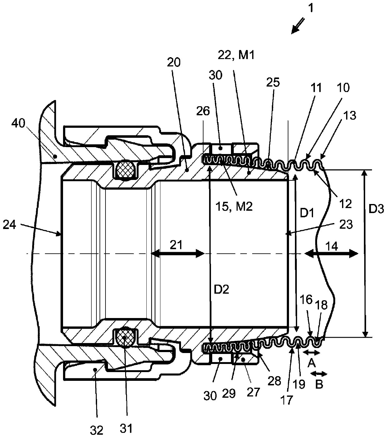
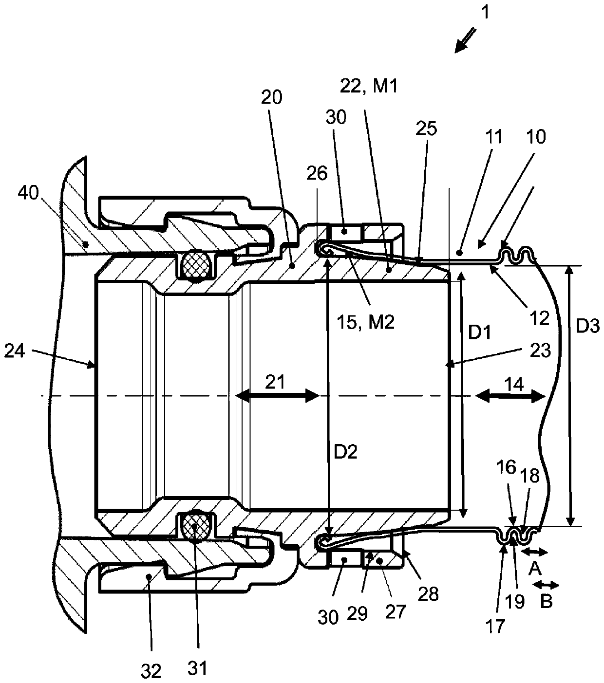
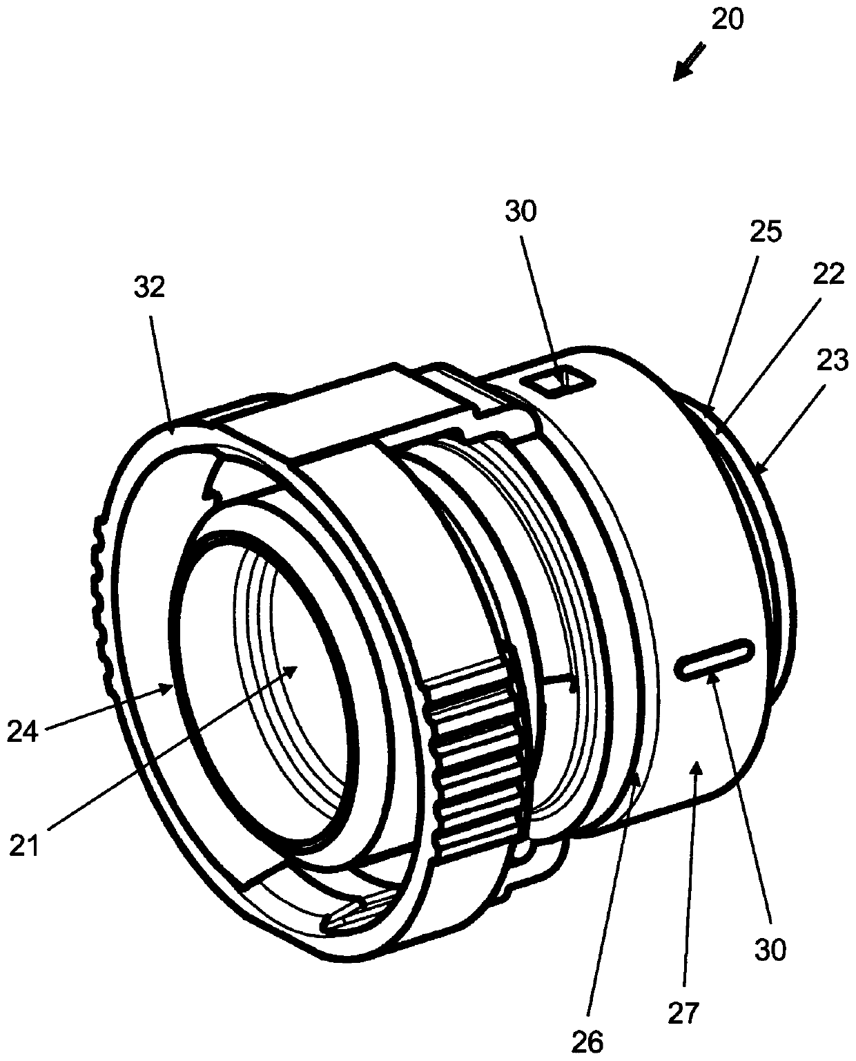
[0036] figure 1 and figure 2 Respectively shows a longitudinal section of a pipe arrangement 1 with a pipe 10, a connecting element 20, or a pipe connection between the pipe 10 and the connecting element 20, the pipe 10 is a corrugated pipe fitting. image 3 In addition, a perspective view of the connecting element 20 is shown.

[0037] according to figure 1 , 2 The connecting element 20 of and 3 forms a through passage 21 extending from a connecting piece 22 to a second opening 24 , and the connecting piece 22 has a first opening 23 . The through channel 21 is straight, which means that the through channel 21 does not produce any direction change. The connecting piece 22 forms an outer peripheral surface 25 and has a stop portion 26 and an outer peripheral collar 27 . An annular gap 28 is formed between the outer peripheral collar 27 and the outer peripheral surface 25 of the connecting member 22 . The annular gap 28 opens in a longitudinal direction and in the direct...


PUM


Abstract

The invention relates to a pipe device (1) comprising a pipe (10) and a connection element (20). The pipe (10) has a pipe jacket (11) that has an inner surface (12) and an outer surface (13) and formsa flow channel (14). The connection element (20) forms a through-channel (21) that extends from a connection piece (22) consisting of a first material (M1) and having a first opening (23) to a secondopening (24). The pipe jacket (11) is positioned on the connection piece (22) with a first pipe end (15) consisting of a second material (M2). A bonded connection is formed between the first material(M1) and the second material (M2) in a contact region between the inner surface (12) of the pipe jacket (11) and a peripheral surface (25) of the connection piece (22).

Description

technical field [0001] According to the preamble of claim 1, the invention relates to a pipe arrangement. Background technique [0002] Various plumbing arrangements known from the prior art comprise a pipe or a line and a connecting element. The connection element is used to connect the pipe to a connection object, for example, a further pipe, a container, a housing, a pump or the like. In most cases, the connection between the pipe and the connecting element is designed so that it cannot be removed repeatedly. In other words, in most cases, the other end of the connecting element is used to provide a quick, easy and removable connection. [0003] Such a pipe arrangement is described, for example, in DE 20 2009 000 328 U1. There is provided a connecting piece for pushing the tube onto the connecting element. A plurality of peripheral support flanges on the connection element prevent the pipe from sliding off the connection once the pipe is pushed. Furthermore, the conn...

Claims


Application Information

Patent Timeline
Patent Type & Authority Applications(China)
IPC IPC(8): F16L13/02F16L13/10F16L25/00F16L33/34F16L47/02B23K20/12B29C65/06
CPCB29C65/0672F16L13/007F16L13/0209F16L13/103F16L25/0036F16L33/34F16L37/0985F16L47/02B29C66/12441B29C66/135B29C66/5344B29L2031/24B29C66/13
Inventor 斯温·库里克
Owner NORMA GERMANY GMBH
Why Eureka
Try Eureka