
Method for broadening bandwidth of waveguide slot non-resonant array antenna

An array antenna and non-resonant technology, applied in design optimization/simulation, etc., can solve problems such as reducing antenna efficiency and increasing dielectric loss, and achieve the effect of widening antenna bandwidth and improving antenna bandwidth

Active Publication Date: 2020-04-24
SHAANXI CHANGLING ELECTRONICS TECH
View PDF5 Cites 0 Cited by
  • Summary
  • Abstract
  • Description
  • Claims
  • Application Information

AI Technical Summary

Problems solved by technology

However, this method of reducing the width of the crack can only broaden the bandwidth of the waveguide crack non-resonant array antenna to a certain extent. When the antenna requires a wider operating frequency band, this method cannot meet the needs
[0007] The second is to widen the bandwidth of the antenna by filling the medium near the crack with the dielectric loading method. The disadvantage of this method is that it increases the dielectric loss and reduces the antenna efficiency.

Method used


Image

  • Method for broadening bandwidth of waveguide slot non-resonant array antenna
  • Method for broadening bandwidth of waveguide slot non-resonant array antenna
  • Method for broadening bandwidth of waveguide slot non-resonant array antenna

Examples


Embodiment Construction

[0026] Embodiments of the present invention will be described in detail below with reference to the accompanying drawings.

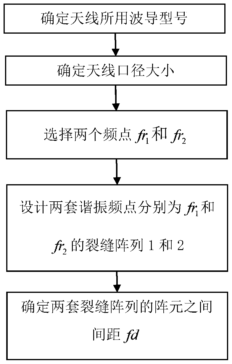
[0027] refer to figure 1 , the implementation steps of the present invention are as follows:

[0028] Step 1. Determine the type of waveguide used by the antenna.

[0029] According to the working frequency band fr of the antenna u ~fr a , according to the frequency band applicable to the standard waveguide, determine the waveguide model.

[0030] In this example, the working frequency band is set to but not limited to 2.7GHz to 3GHz, and the waveguide model is determined to be BJ32.

[0031] Step 2. Determine the size L of the antenna aperture.

[0032] Antenna aperture size L and working frequency band fr u ~fr a , lobe width θ, and sidelobe level η are related, and are determined by the following formula:

[0033]

[0034] In the formula, λ u is the resonant frequency point fr u free-space wavelength at is the beam broadening factor, ...


PUM


Abstract

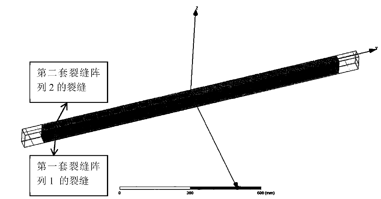
The invention discloses a method for broadening the bandwidth of a waveguide slot non-resonant array antenna. The method mainly solves the problem that an existing waveguide slot non-resonant array antenna is narrow in working band. The implementation scheme is as follows: selecting two working frequency points fr1 and fr2 of which the frequencies are staggered from each other in the working frequency band of the antenna; changing an array element of the waveguide slot non-resonant array antenna from an existing single slot into double slots of which the resonant frequencies are fr1 and fr2 respectively, namely, two sets of crack arrays with different resonant frequencies are designed on the same waveguide aperture surface according to a known waveguide crack array antenna design method and formula to broaden the bandwidth of the antenna, and a distance fd is arranged between array elements of the two sets of crack arrays, so that the two sets of crack arrays do not interfere with eachother. The bandwidth of the waveguide slot non-resonant array antenna can be effectively broadened, and the method can be used for designing the waveguide slot non-resonant array antenna.

Description

technical field [0001] The invention belongs to the field of radar antennas, in particular to a method for widening the bandwidth of the antenna, which can be used in the design of waveguide slot non-resonant array antennas. Background technique [0002] The surface field distribution of the waveguide slot array antenna can be precisely controlled, and it is easy to achieve the requirements of high efficiency, high gain, extremely low sidelobe, narrow beam and shaped beam; and its feed system and radiation system are integrated, so that it has Low profile characteristics; the above-mentioned characteristics of the waveguide slot array antenna make it widely used in the field of radar, especially in space radar. [0003] With the emergence of complex electromagnetic environments such as electronic interference, in order to improve the adaptability of radar to electromagnetic environments, a series of anti-interference technologies such as frequency conversion and frequency mo...

Claims


Application Information

Patent Timeline
Patent Type & Authority Applications(China)
IPC IPC(8): G06F30/20
CPCY02D30/70
Inventor 郑翕文刘晓萍高文斌焦磊汪贵明张泽宇彭良张雯
Owner SHAANXI CHANGLING ELECTRONICS TECH
Learn More