
Pinch roll oil-seal-free speed reducer for steel industry

A technology of pinch rollers and reducers, which is applied in the direction of mechanical equipment, transmission parts, belts/chains/gears, etc., can solve the problems of easy aging, affecting sealing performance and service life, dust ingress, etc., to avoid high temperature aging, Good sealing and dustproof effect, simple structure

Pending Publication Date: 2020-04-24
JIANGSU TAILONG MACHINERY GRP CO CO LTD
View PDF0 Cites 1 Cited by
  • Summary
  • Abstract
  • Description
  • Claims
  • Application Information

AI Technical Summary

Problems solved by technology

The requirements for the reducer are getting higher and higher. For the steel industry, due to the special environment of high temperature and dust, the oil seal structure adopted by the traditional reducer is easy to age or enter dust after long-term use, which will affect the sealing performance and The service life has been unable to meet the increasing performance requirements of mechanical equipment

Method used


Image

  • Pinch roll oil-seal-free speed reducer for steel industry
  • Pinch roll oil-seal-free speed reducer for steel industry
  • Pinch roll oil-seal-free speed reducer for steel industry

Examples


Embodiment Construction

[0016] Further description will be made below in conjunction with drawings and embodiments.

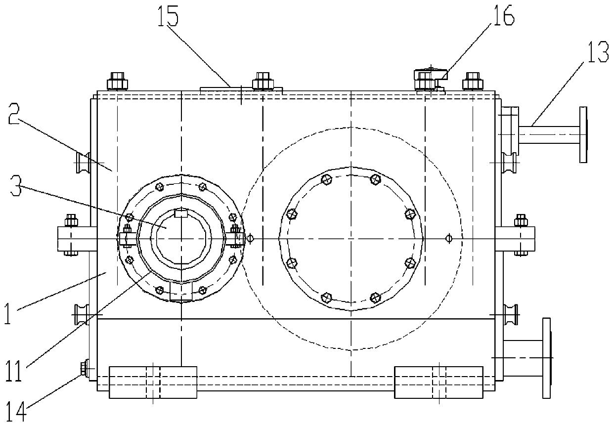
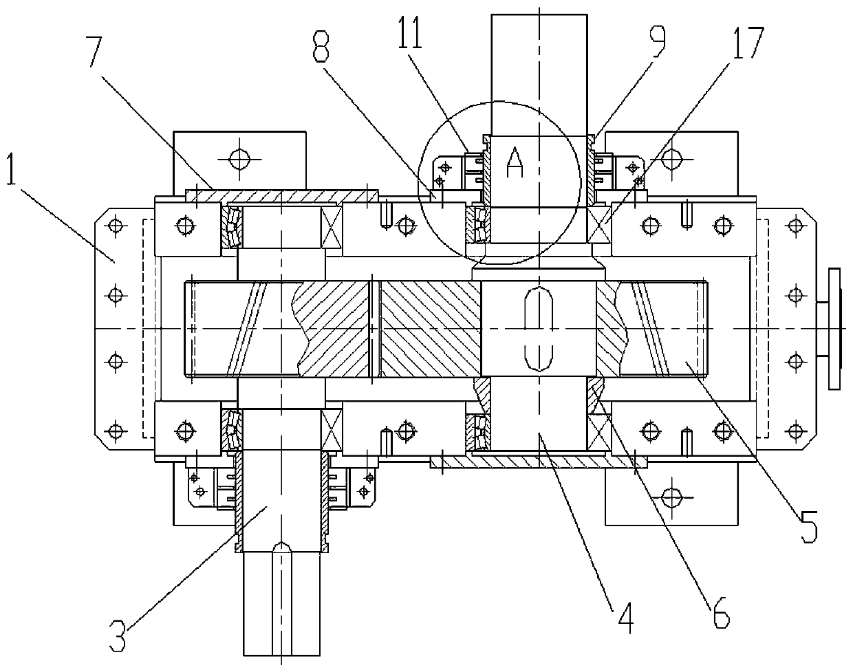
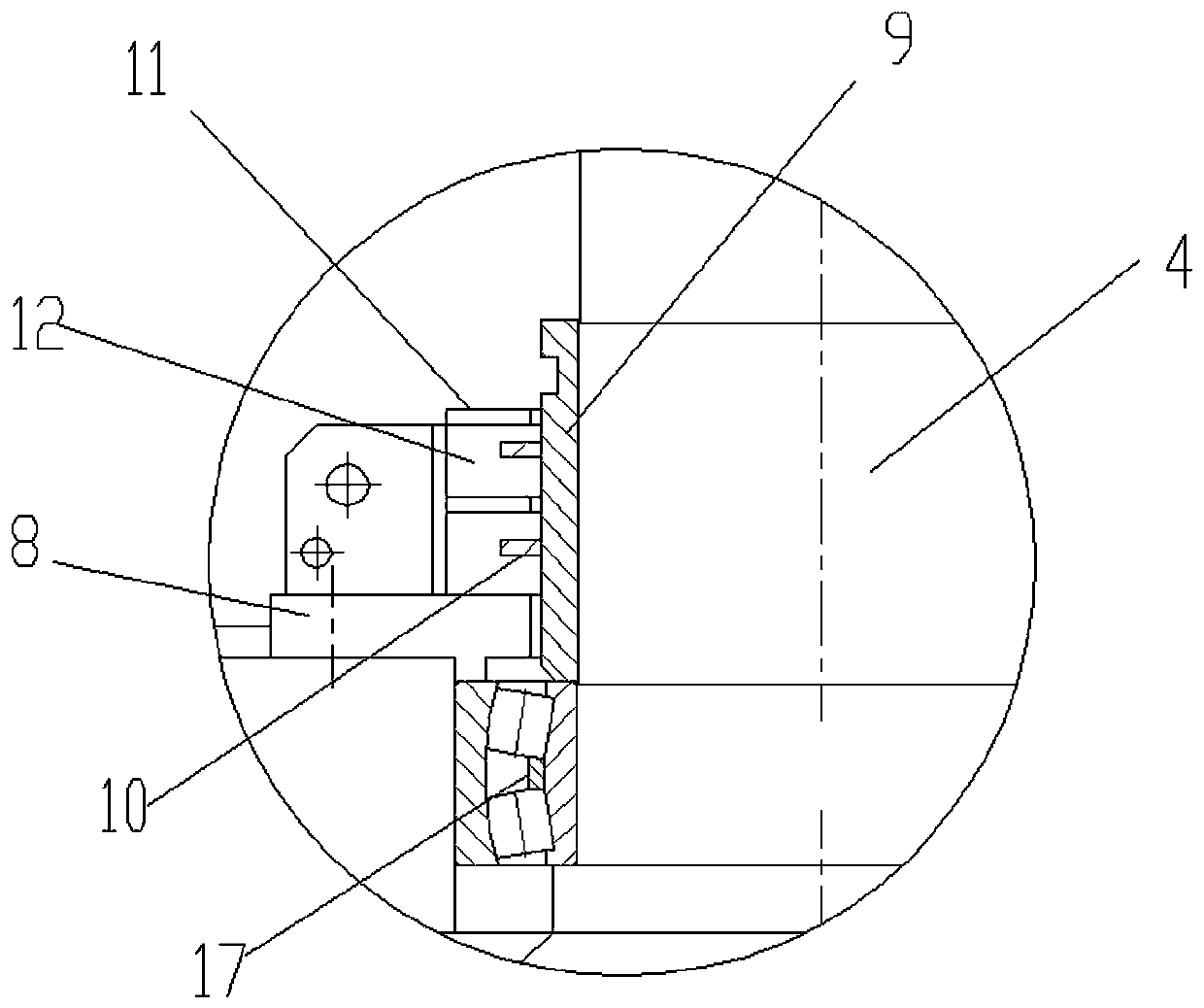
[0017] figure 1 , 2 , 3 shows: an oil-seal-free reducer for pinch rollers in the iron and steel industry includes a box body 1, a box cover 2, an input shaft 3, an output shaft 4, a gear 5, a spacer ring 6, a stuffy cover 7, and a transparent cover 8 , Oil throwing ring 9, oil throwing ring sheet 10, semicircular oil throwing shell 11, inlet / release pipeline 13, screw plug 14, sight hole cover 15, ventilation cover 16. The input shaft 3 and the output shaft 4 protrude from the box body 1 in opposite directions and are covered by the box cover 2. One end of the input shaft 3 is encapsulated by the stuffy cover 7, and the other end penetrates the through cover 8, and the input shaft is crimped on the box body through the cover. The supporting bearing 17, the oil throwing ring 9 is sleeved on the input shaft outside the supporting bearing, and more than two oil throwing ring pieces 10 ...


PUM


Abstract

The invention relates to a pinch roll oil-seal-free speed reducer for the steel industry. One end of an input shaft is sealed through a closed cover, and the other end is in penetrating connection with a through cover. The through cover is in pressing connection with a supporting bearing, on a box, of the input shaft. The part, outside the supporting bearing, of the input shaft is in cup joint with an oil slinger, and two or more oil slinger sheets are evenly distributed on the outer side of the oil slinger in the axial direction. The shaft section of the part, outside the through cover, of the input shaft is in hooping connection with and locks an upper oil shedding shell and a lower oil shedding shell through bolts. Each of the upper oil shedding shell and the lower oil shedding shell isinternally provided with two or more sections of semicircular oil shedding cavities in the axial direction of the input shaft. A complete circular oil shedding cavity is formed by every two semicircular oil shedding cavities, wherein the side wall of the oil shedding cavity is in clearance fit with the outer circumference wall of the oil slinger. Each cavity contains one oil slinger sheet, and the oil slinger sheets make contact with the cavity bottoms of the semicircular oil shedding cavities. An output shaft is in penetrating connection with a through cover structure the same with the inputshaft. The pinch roll oil-seal-free speed reducer is compact in structure and suitable for being safely sealed and used in the steel industry environment.

Description

technical field [0001] The invention relates to a speed reducer, in particular to a speed reducer without an oil seal for pinch rollers in the iron and steel industry. Background technique [0002] With the rapid development of my country's industrial technology, reducers are widely used in mechanical equipment in metallurgy, mining, chemical industry, construction, agriculture, transportation, power generation and other industries. The requirements for the reducer are getting higher and higher. For the steel industry, due to the special environment of high temperature and dust, the oil seal structure adopted by the traditional reducer is easy to age or enter dust after long-term use, which will affect the sealing performance and The service life has been unable to meet the increasing performance requirements of mechanical equipment. Contents of the invention [0003] The invention provides an oil-seal-free speed reducer for pinch rollers in the iron and steel industry, w...

Claims


Application Information

Patent Timeline
Patent Type & Authority Applications(China)
IPC IPC(8): F16H57/021F16H57/023F16H57/029
CPCF16H57/021F16H57/023F16H57/029F16H2057/02069
Inventor 陆晓妹孙健康宝刚翁燕张梅红殷庆凤
Owner JIANGSU TAILONG MACHINERY GRP CO CO LTD
Learn More