
Spot welding machine with six-axis robot

A six-axis robot and spot welding machine technology, applied in welding equipment, resistance welding equipment, metal processing equipment and other directions, can solve the problems of high work intensity and low production efficiency, and achieve improved product quality, easy welding, and convenient operation. Effect

Inactive Publication Date: 2018-12-07
XIANGYANG TRADETOOL AUTOMOBILE PARTS
View PDF6 Cites 0 Cited by
  • Summary
  • Abstract
  • Description
  • Claims
  • Application Information

AI Technical Summary

Problems solved by technology

[0002] Most of the existing spot welding machines are manually operated, with high working intensity, low production efficiency, and certain dangers. In addition, it is not convenient to carry out comprehensive welding on the workpieces that need to be welded.

Method used


Image

  • Spot welding machine with six-axis robot
  • Spot welding machine with six-axis robot

Examples


Embodiment 1

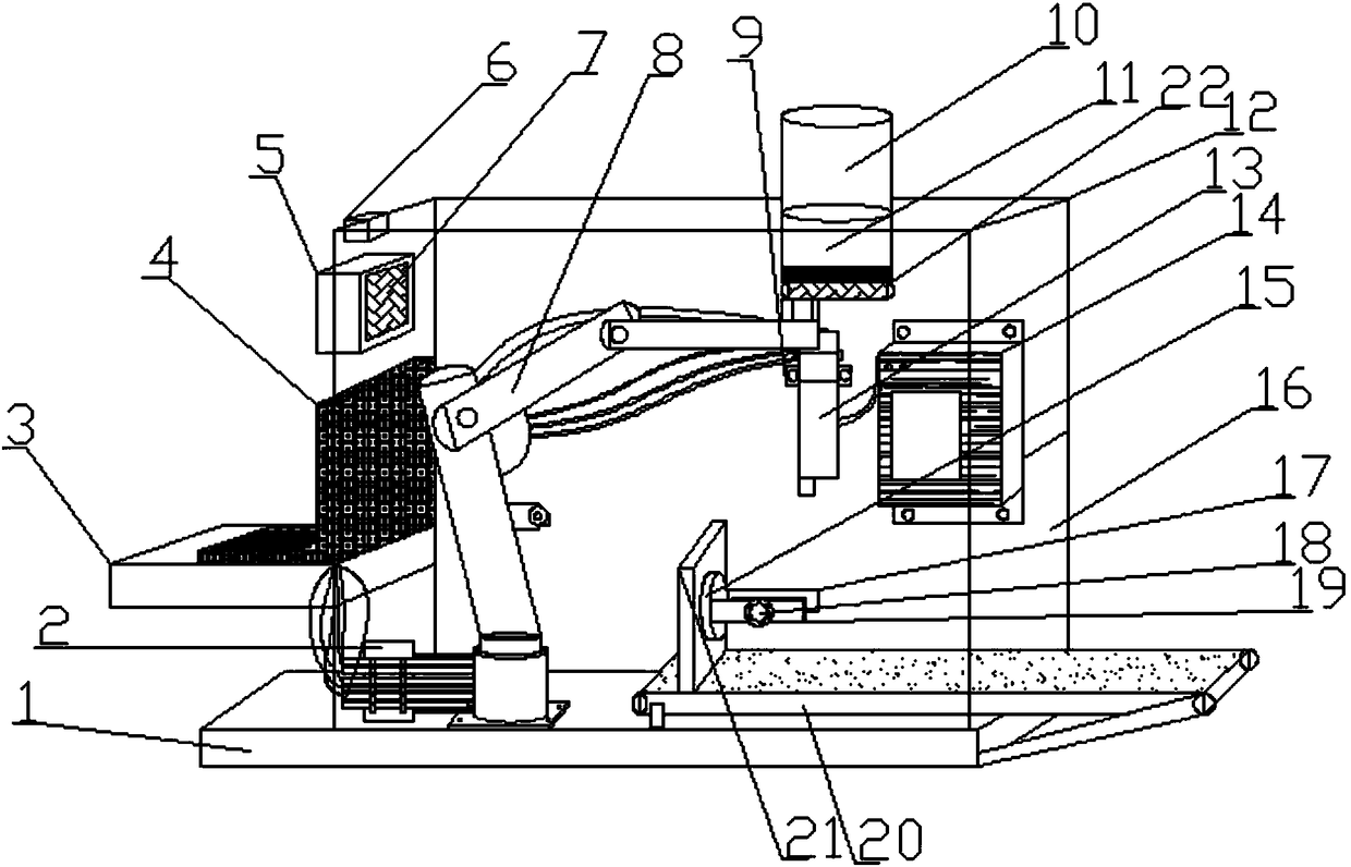
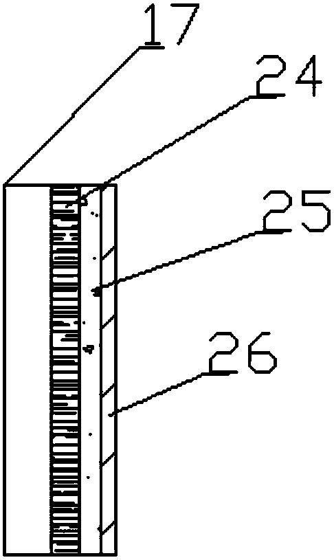
[0022] Such as Figure 1-2 As shown, a spot welding machine with a six-axis robot includes a base 1, a conveyor belt body 20, a six-axis robot body 8 and an automatic electric welding machine main body 14, and the top of the base 1 is equipped with a protective cover 12 by bolts, so One side of the protective cover 12 is provided with a placement platform 3 through a mounting piece, and the upper end of the placement platform 3 is provided with an air inlet 5, and a small cooling fan 7 is installed through a mounting seat in the air inlet 5, and the protective cover 12 The other side is provided with a feed port 16, the conveyor belt body 20 runs through the feed port 16, and one end of the top of the conveyor belt body 20 is equipped with a mounting plate 21 through a bolt, and one side of the mounting plate 21 is provided with an electric motor through a screw. Turntable 15, one side of the electric turntable 15 is provided with a limit clamp 17 through a fixing member, a fi...

Embodiment 2

[0038] Such as Figure 1-2 As shown, a spot welding machine with a six-axis robot includes a base 1, a conveyor belt body 20, a six-axis robot body 8 and an automatic electric welding machine main body 14, and the top of the base 1 is equipped with a protective cover 12 by bolts, so One side of the protective cover 12 is provided with a placement platform 3 through a mounting piece, and the upper end of the placement platform 3 is provided with an air inlet 5, and a small cooling fan 7 is installed through a mounting seat in the air inlet 5, and the protective cover 12 The other side is provided with a feed port 16, the conveyor belt body 20 runs through the feed port 16, and one end of the top of the conveyor belt body 20 is equipped with a mounting plate 21 through a bolt, and one side of the mounting plate 21 is provided with an electric motor through a screw. Turntable 15, one side of the electric turntable 15 is provided with a limit clamp 17 through a fixing member, a fi...


PUM


Abstract

The invention discloses a spot welding machine with a six-axis robot. The spot welding machine with the six-axis robot comprises a base, a conveying belt body, a six-axis robot body and an automatic electric welding machine main body, wherein a protection cover is installed at the top of the base through a bolt; a placement table is arranged at one side of the protection cover through an installation element, and an air inlet port is formed in the upper end of the placement table; a small cooling fan is installed in the air inlet port through an installation seat; a charge port is formed in the other side of the protection cover; the conveying belt body penetrates through the charge port; an installation plate is installed at one end of the top of the conveying belt body through a bolt; anelectric rotary table is arranged at one side of the installation plate through a screw; a limit clamp is arranged at one side of the electric rotary table through a fixing element; and a fixed plateis arranged at the inner side of the limit clamp. The spot welding machine with the six-axis robot is various in function, simple to operate, and convenient to produce, meets many needs in a use process, and is suitable for being widely popularized.

Description

technical field [0001] The invention relates to the technical field of industrial production, in particular to a spot welding machine with a six-axis robot. Background technique [0002] Existing spot welding machines are mostly operated manually, with high work intensity, low production efficiency, and certain dangers. In addition, it is inconvenient to fully weld the workpieces that need to be welded. For this purpose, we propose a spot welding machine with a six-axis robot. Contents of the invention [0003] The main purpose of the present invention is to provide a spot welding machine with a six-axis robot, which can effectively solve the problems in the background technology. [0004] In order to achieve the above object, the technical scheme that the present invention takes is: [0005] A spot welding machine with a six-axis robot, including a base, a conveyor belt body, a six-axis robot body and an automatic electric welding machine body, a protective cover is ins...

Claims


Application Information

Patent Timeline
Patent Type & Authority Applications(China)
IPC IPC(8): B23K11/11B23K11/36
CPCB23K11/11B23K11/36
Inventor 刘小军
Owner XIANGYANG TRADETOOL AUTOMOBILE PARTS
Learn More