Piston material pushing centrifugal machine and feeding method thereof

A centrifuge and piston technology, applied in the field of centrifuges, can solve the problems of fewer stages of drums, high moisture content of materials, cracking of drum bottoms, etc., and achieve long filtration area, low moisture content of filter residues, and increase filtration time Effect

Pending Publication Date: 2020-04-24
武汉德泽环保科技有限公司
View PDF9 Cites 1 Cited by
  • Summary
  • Abstract
  • Description
  • Claims
  • Application Information

AI Technical Summary

Problems solved by technology

The cantilever structure causes the free end of the drum to vibrate under the joint action of forces parallel to the axial direction and perpendicular to the axial direction. In severe cases, the bottom of the drum at the fixed end of the drum cracks, causing serious accidents
[0009] The mechanical characteristics of unilateral support and cantilever structure limit the diameter, rotation speed, length of the filter area, and the increase of the number of stages of the drum, which in turn leads to easy vibration of the piston pusher centrifuge, small separation factor, and short material filtration time , The moisture content of the material is too high, the drying energy consumption per unit of product is large, the washing water equivalent is too large, the washing water treatment after use is difficult, the environmental protection cost is increased, the number of drum stages is too small, the production capacity is too small, and it cannot be large-scaled, etc. shortcoming

Method used


Image

  • Piston material pushing centrifugal machine and feeding method thereof
  • Piston material pushing centrifugal machine and feeding method thereof
  • Piston material pushing centrifugal machine and feeding method thereof

Examples


Embodiment 1

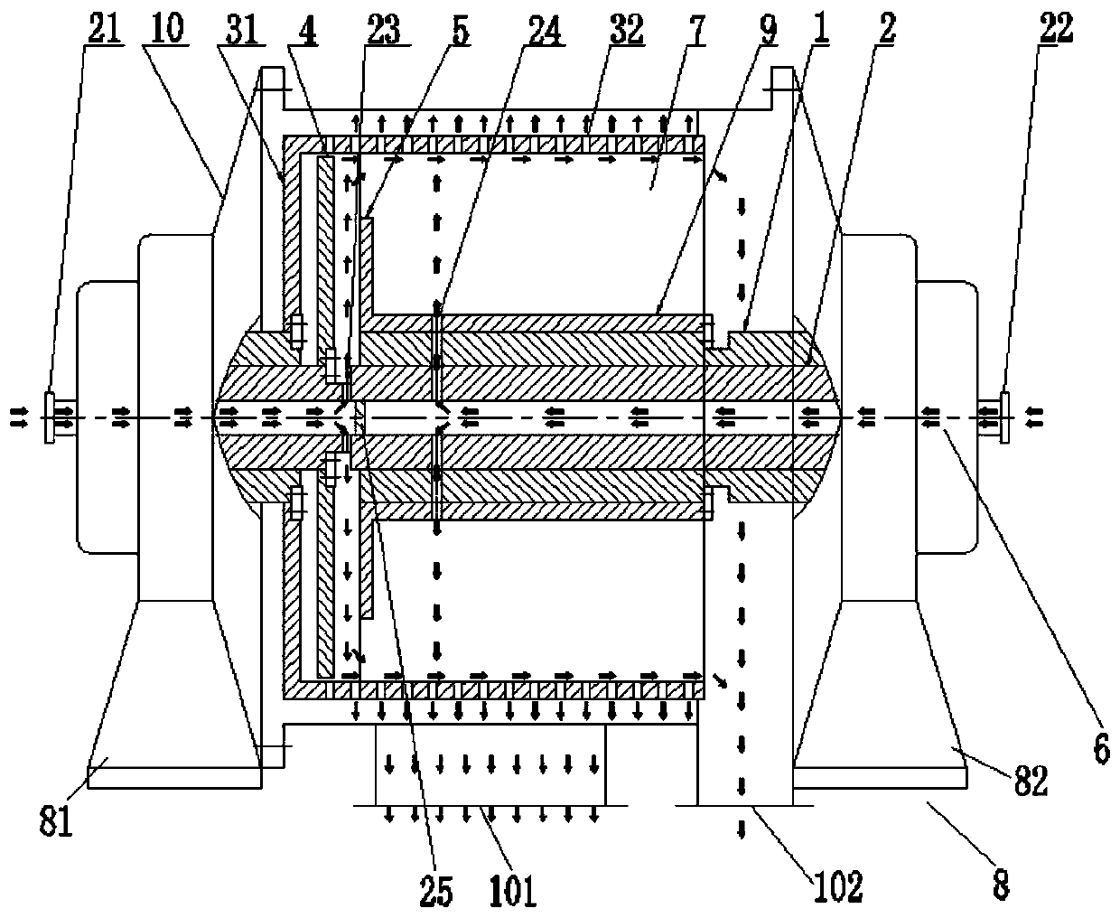
[0036] Please refer to figure 1 , a piston pusher centrifuge, including a main shaft 1, a push rod 2, a drum 3 with one end open and a hole in the side wall, a pusher 4, a distributor 5, a driving mechanism 6, a drum reinforcement structure 7, a main shaft The supporting structure 8, the sleeve 9 and the casing 10 arranged outside the drum 3, the lower end of the casing 10 is provided with a filtrate outlet 101 and a filter residue outlet 102;

[0037]The main shaft support structure 8 includes a left support structure 81 and a right support structure 82 respectively arranged on both sides of the drum; the drum bottom 31 of the drum 3 is fixedly arranged on the main shaft 1 or the push rod 2, and the drum strengthens The structures 7 are all arranged in the circumferential direction of the sleeve 9, one end of the drum strengthening structure 7 is fixed on the sleeve 9, and the other end is fixed on the drum wall 32 of the drum 3;

[0038] The push rod 2 is a hollow tubular s...

Embodiment 2

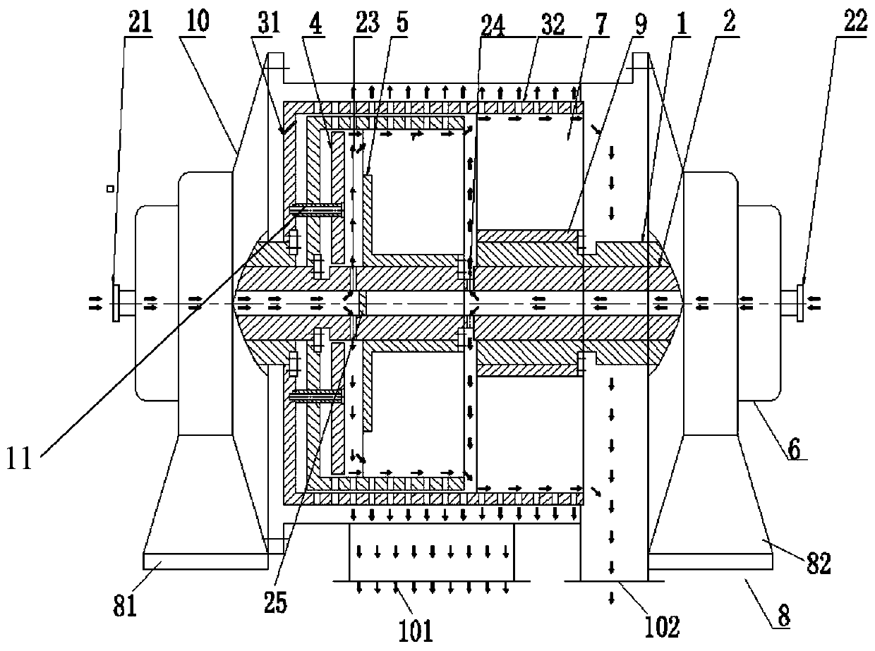
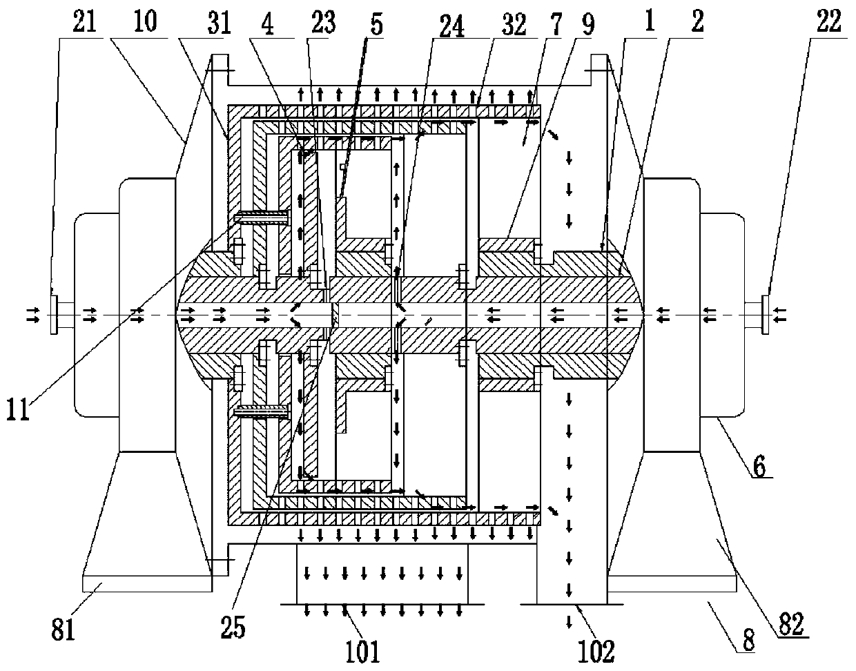
[0043] Different from Embodiment 1, the number of the drum reinforcing structures 7 distributed axially in the drum can be two rows (see figure 2 , image 3 , Figure 5 ), which are respectively positioned at the axial feed end and the discharge end of the drum wall 32, become a simply supported beam support structure supported by double fulcrums; it can be a plurality of more than two rows (see Figure 6 ), which are respectively located between the axial feed end and the discharge end of the drum wall 32, and become a multi-fulcrum support structure.

Embodiment 3

[0045] The difference from Embodiment 1 is that the material channel 23 or the washing water channel 24 is other structural forms such as annular seams on the push rod 2, and the two ends of the annular seams are connected by the connecting structure 11. At this time, the torque of the driving mechanism is Structure 11 transfer (see figure 2 , image 3 , Figure 4 , Figure 5 , Figure 6 , Figure 9 area with connection structure 11). The connection structure 11 can be a combination of a single or multiple fasteners (such as screws, bolts) of a plate, a column, a pipe, or a combination of multiple single or multiple fasteners (such as similar to a joint shaft structure).


PUM


Abstract

The invention discloses a piston material pushing centrifugal machine. The machine comprises a main shaft, a push rod, a rotary drum, a pusher, a distributor, a driving mechanism, a rotary drum reinforcing structure, a main shaft supporting structure, a sleeve and a machine shell arranged outside the rotary drum; one end of the rotary drum reinforcing structure is fixed to the sleeve, and the other end of the rotary drum reinforcing structure is fixed to the rotary drum wall of the rotary drum; the push rod is of a hollow tubular structure, a material channel communicating with an internal pipeline of the push rod is arranged on the position, between the pusher and the distributor, of the main shaft and / or the push rod, and materials enter a gap between the pusher and the distributor through the material channel and then enter the interior of the rotary drum; and a washing water channel communicating with the interior of the push rod is formed in the middles of the main shaft, the pushrod and the sleeve, and washing water enters the interior of the rotary drum through the washing water channel. According to the machine, through a multi-point supporting structure and an unique feeding method, the rotary drum is large in diameter, high in rotating speed, long in filtering area length, and large in rotary drum stage number, and the advantages that the vibration is not prone to occur, the separation factor is large, the water content of filter residue is low, the water equivalent of the washing water is small, the production capacity is large, and the enlargement is availableare achieved.

Description

technical field [0001] This patent relates to a centrifuge, specifically a piston pusher centrifuge and a feeding method thereof. Background technique [0002] The conventional piston pusher centrifuge is a continuous operation, pulsating discharge filter centrifuge. In the case of high-speed operation, the material is continuously fed from the feed pipe at the open end of the drum, and flows along the feed distributor to the screen of the drum. The filtrate passes through the filter screen and is discharged continuously through the filtrate outlet, and the filter residue accumulated on the inner surface of the filter screen is pushed out along the inner wall of the drum by the pusher that reciprocates relative to the drum. [0003] Since the material is fed from the feed pipe at the open end of the drum, the support of the main shaft of the conventional piston pusher centrifuge can only be made into a unilateral support structure, and the supporting structure is that the t...

Claims


Application Information

Patent Timeline
Patent Type & Authority Applications(China)
IPC IPC(8): B04B11/02B04B7/08B04B9/04B04B1/00
CPCB04B11/02B04B7/08B04B9/04B04B1/00
Inventor 张颖芃陈子豪李佳璇
Owner 武汉德泽环保科技有限公司
Why Eureka
Try Eureka