Mobile phone camera module surface inspection fixture

A camera module and surface detection technology, which is applied in image communication, television, branch office equipment, etc., can solve the problems of long time spent and achieve the effect of improving production efficiency and avoiding damage

Active Publication Date: 2021-07-20
SHINE OPTICS TECH CO LTD
View PDF7 Cites 0 Cited by
  • Summary
  • Abstract
  • Description
  • Claims
  • Application Information

AI Technical Summary

Problems solved by technology

The traditional inspection device can only inspect the lens, and after the inspection is completed, the camera needs to be transported, which takes a long time

Method used


Image

  • Mobile phone camera module surface inspection fixture
  • Mobile phone camera module surface inspection fixture
  • Mobile phone camera module surface inspection fixture

Examples


Embodiment 1

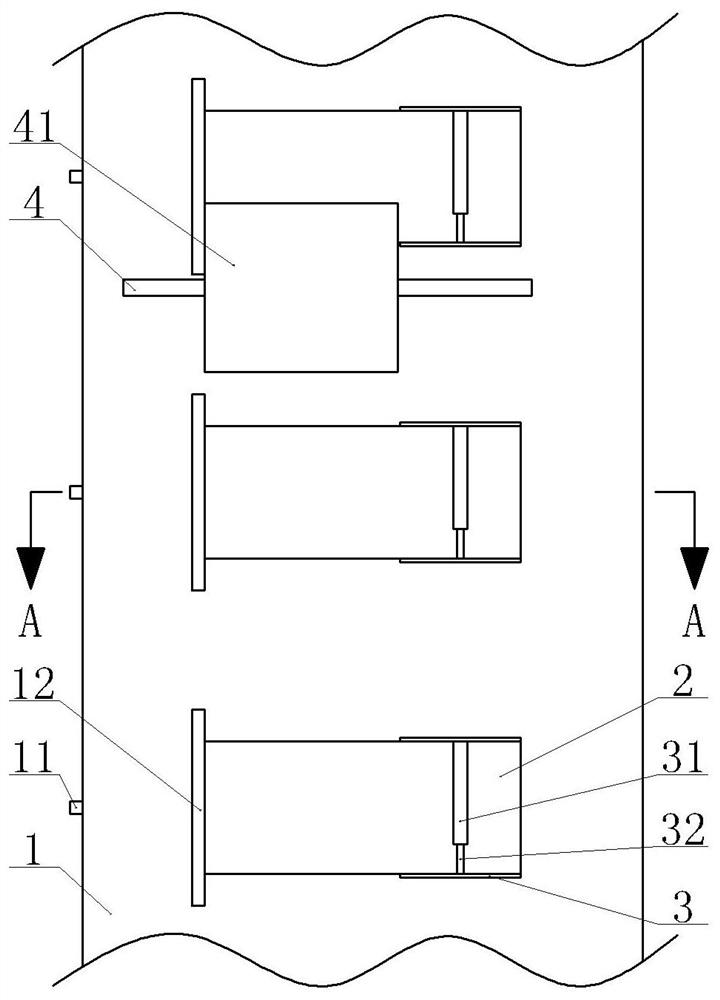
[0034] Mobile phone camera module surface inspection fixture, such as figure 1 As shown, it includes a frame, a driving part, a conveyor belt 1 and a pressing part. The frame is provided with two rotating shafts, both of which are arranged horizontally and both of which run through the frame and are matched with the frame. The two rotating shafts A driving wheel and a driven wheel are respectively arranged on the top, and the driving wheel, the driven wheel and the conveyor belt 1 constitute a conveyor belt mechanism. The driving member is fixed on the frame by bolts and connected with the rotating shaft where the driving wheel is located through a shaft coupling.

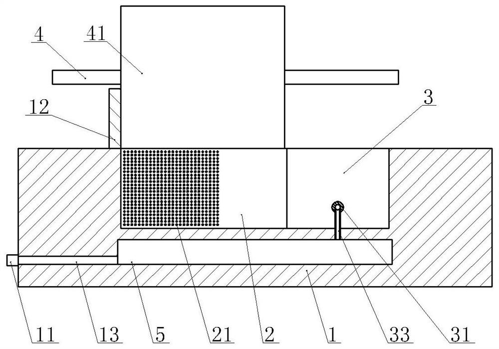
[0035] The conveyor belt 1 is provided with several detection units along the length direction of the conveyor belt 1, such as figure 2 As shown, the detection unit includes a detection groove 2 and an air intake pipe 13. The length of the detection groove 2 is greater than the sum of the lens of the camera and t...

Embodiment 2

[0044] On the basis of Example 1, such as Figure 4 As shown, the conveyor belt 1 in this embodiment is vertically provided with a push-out chamber 6, the push-out chamber 6 is located below the lens accommodation area and below the pressurized chamber 5, the upper end of the push-out chamber 6 communicates with the pressurized chamber 5, and the push-out chamber A piston 61 is arranged transversely in the interior of the piston 6, and the piston 61 is slidingly sealed with the ejection chamber 6. The piston 61 separates the push-out chamber 6 into an upper slide-down chamber and a lower push-up chamber. A spring 65 is arranged in the push-up chamber, and the two ends of the spring 65 are welded to the bottom of the push-up chamber and the piston 61 respectively. A push rod 62 is glued vertically on the piston 61, and the upper end of the push rod 62 runs through the bottom of the conveyor belt 1 and extends into the detection tank 2; a ring-shaped positioning block 63 is arra...


PUM


Abstract

The invention relates to the field of mobile phone components, and specifically discloses a surface detection jig for a camera module of a mobile phone. It includes a driving part and a conveyor belt. The driving part drives the conveyor belt to move. There are several detection units along the length direction of the conveyor belt. The detection unit includes a detection slot and an air intake pipe. The depth of the lens is the same as the depth of the lens. There is a pressing piece on the top of the conveyor belt that is close to the upper surface of the conveyor belt; the side wall of the detection tank is provided with a ring-shaped pressurized chamber. The air inlet pipe is connected with the pressurized chamber and fixed with the conveyor belt. A pressure sensor is arranged in the chamber, a brush electrically connected with the pressure sensor is arranged on the surface of the conveyor belt, and a pressure hole communicating with the pressure chamber is arranged on the side wall of the detection groove opposite to the lens. The detection jig of the present invention can detect the surface of the camera while being transported.

Description

technical field [0001] The invention relates to the field of mobile phone components, in particular to a surface detection jig for a camera module of a mobile phone. Background technique [0002] The current smartphones are equipped with cameras. In order to ensure the quality of the cameras, they need to be inspected one by one after the cameras are assembled. Now that the production of mobile phones is relatively large, there are as few as one camera installed on each mobile phone, and as many as five. , six. The camera includes a lens and a circuit board. In order to facilitate installation and ensure a long service life of the camera, the surface of the lens needs to be inspected to ensure that the surface of the lens is smooth, flat and free of cracks. The traditional inspection device can only inspect the lens, and after the inspection is completed, the camera needs to be transported, which takes a long time. Contents of the invention [0003] The object of the pre...

Claims


Application Information

Patent Timeline
Patent Type & Authority Patents(China)
IPC IPC(8): H04N17/00H04M1/24
CPCH04M1/24H04N17/00
Inventor 关红党何阿强
Owner SHINE OPTICS TECH CO LTD
Why Eureka
Try Eureka