
Centralized winding motor coil fixing structure and assembling method

A technology of winding coil and fixed structure, applied in the field of fixed structure and assembly of centralized winding motor coil, can solve the problems of restricting production capacity, unable to reuse and recycle, and many potting processes, so as to reduce the raw material and processing cost of the motor, shorten the Production and processing cycle, the effect of reducing environmental pollution

Active Publication Date: 2020-04-21
JIANGSUSNGQI GROUP
View PDF7 Cites 2 Cited by
  • Summary
  • Abstract
  • Description
  • Claims
  • Application Information

AI Technical Summary

Problems solved by technology

This type of motor has many stator potting processes, and the processing time usually accounts for 30% of the total processing time of the motor. The production efficiency is low, which seriously restricts the production capacity.
[0004] 2. After the stator is potted, in the inspection of the subsequent process, if the winding short circuit, open circuit, poor inter-turn, serious potting defects or other bad problems are found, the stator can no longer be repaired, resulting in the scrapping of the stator and the product is qualified rate is lower, which ultimately increases production costs
[0005] 3. The potting glue used for stator potting is a chemical product, which cannot be reused and recycled after curing, and a certain amount of solid waste will be generated during the potting process. In addition, special equipment is required for heating during the curing process of the potting glue, which consumes a lot of energy. higher
Therefore, the currently used potting process does not conform to the trend of environmental protection development, and process improvement is required

Method used


Image

  • Centralized winding motor coil fixing structure and assembling method
  • Centralized winding motor coil fixing structure and assembling method
  • Centralized winding motor coil fixing structure and assembling method

Examples


Embodiment Construction

[0040] The present invention will be further described in detail below in conjunction with the accompanying drawings and specific preferred embodiments.

[0041] In the description of the present invention, it should be understood that the orientations or positional relationships indicated by the terms "left side", "right side", "upper", "lower" are based on the orientations or positional relationships shown in the accompanying drawings, and are only For the purpose of describing the present invention and simplifying the description, rather than indicating or implying that the device or element referred to must have a specific orientation, be constructed and operate in a specific orientation, "first", "second" and the like do not represent components importance, and therefore should not be construed as limiting the invention. The specific dimensions used in this embodiment are only for illustrating the technical solution, and do not limit the protection scope of the present in...


PUM


Abstract

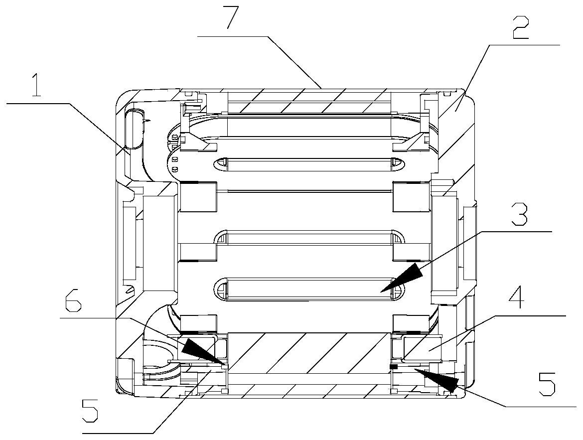
The invention discloses a centralized winding motor coil fixing structure and an assembling method. The centralized winding motor coil fixing structure comprises a stator iron core, centralized winding coils, end covers and supporting structural members; the supporting structural members are located between the stator iron core and the end covers on two sides; each supporting structural member comprises a fixing circular ring and coil positioning teeth with the same number as stator teeth; each coil positioning tooth comprises a triangular support and a lengthened fixing boot; the two isosceles sides of each triangular support is used for circumferentially limiting the coil of the corresponding centralized winding coil; and the two bottom surfaces of each lengthened fixing boot radially limit the frame plane of the corresponding centralized winding coil. According to the centralized winding motor coil fixing structure and the assembling method of the invention, the stator teeth are straight teeth, so that the batch winding of the centralized winding coils can be completed on the outer sides of the stator teeth; and the centralized winding coils are fixed in the radial direction andthe circumferential direction through the supporting structural members, and therefore, a pouring sealant can be omitted. Thus, a production period can be shortened by at least 20%, production efficiency can be improved by 65%, and production cost can be reduced by 25%.

Description

technical field [0001] The invention relates to the field of concentric winding motors, in particular to a coil fixing structure and assembly method of a centralized winding motor. Background technique [0002] The existing centralized winding motor adopts the process of stator potting to fix the winding and conduct heat. Due to the following reasons, the processing cycle of this type of motor is long, the production efficiency is low, the pass rate is low, and the cost is high. And There are environmental issues. [0003] 1. After the coil of this type of motor is wound on the special winding equipment, it is stuffed into the special potting and shaping tool, and the coil is bound and welded by hand, and then the stator is preheated as a whole. The preheating time is usually not less than one hour, and then the The potting is carried out in time and in sections, and the potting can not be in place at one time. It is necessary to control the potting speed, and at the same t...

Claims


Application Information

Patent Timeline
Patent Type & Authority Applications(China)
IPC IPC(8): H02K1/12H02K3/46H02K15/08H02K15/12
CPCH02K1/12H02K3/46H02K15/08H02K15/12
Inventor 印光宇王雨徐兆明冯满君
Owner JIANGSUSNGQI GROUP
Learn More