Remote automatic control system
An automatic control system and remote technology, applied in the direction of control/adjustment system, non-electric variable control, ratio control, etc., can solve the problems of inaccurate measurement of natural gas concentration, unreliable alarm, etc., and achieve small error, high precision, and precise Effect of alarm data
- Summary
- Abstract
- Description
- Claims
- Application Information
AI Technical Summary
Problems solved by technology
Method used
Image
Examples
Embodiment 1
[0024] The embodiment of the remote automatic control system of the present invention is basically as attached figure 1 As shown, including the detection module, judgment module, alarm module, remote module and cloud camera, where the cloud camera is not in figure 1 drawn in.
[0025] The detection module includes two Risym 16MM ultrasonic sensors (transceivers), MDT2030S microcontroller, VMS-300C3-WS-GPRS temperature sensor, BMP280-3.3 pressure sensor and DSP56301PW80 DSP processor. The positions of the two ultrasonic sensors are fixed, and the distance between them is L. One of the ultrasonic sensors sends a pulse signal to the other ultrasonic sensor, and when the ultrasonic wave is emitted, the single-chip microcomputer is started to count immediately. When the single-chip microcomputer detects that the amplitude of the received signal exceeds the reference threshold, it stops counting immediately. At this time, the count value N can be read from the microcontroller. A...
Embodiment 2
[0057] The only difference from Embodiment 1 is that a high-definition cloud camera is also installed at the gas filling station, and the cloud camera is connected to the server of the remote module through a wireless network. When the concentration of natural gas in the air is greater than the lower limit of explosive concentration, the power trigger mechanism of the cloud camera will be powered on, and then the cloud camera will start to shoot video in the gas filling station, and send the captured video to the display screen of the remote module. This is convenient for the staff to observe the actual situation in the filling station in real time.
Embodiment 3
[0059] The only difference from Example 2 is:
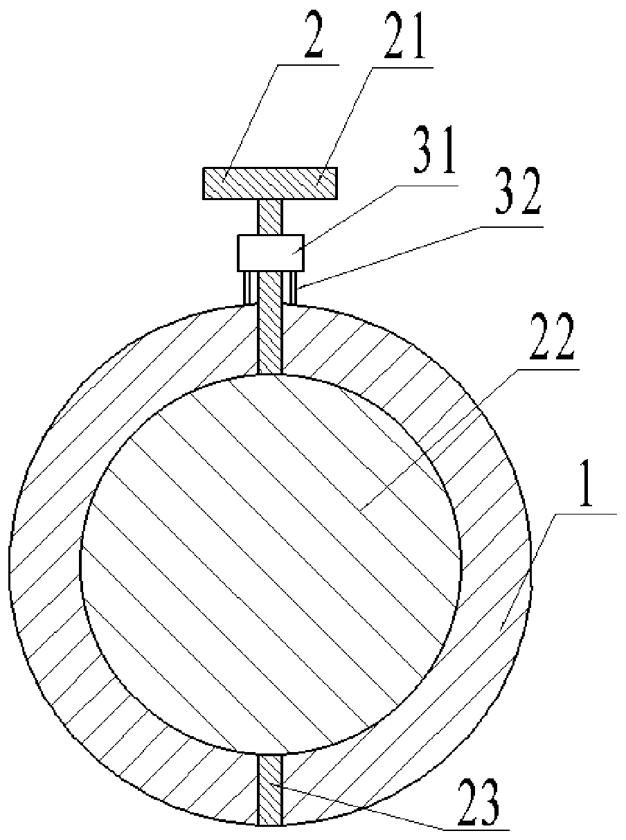
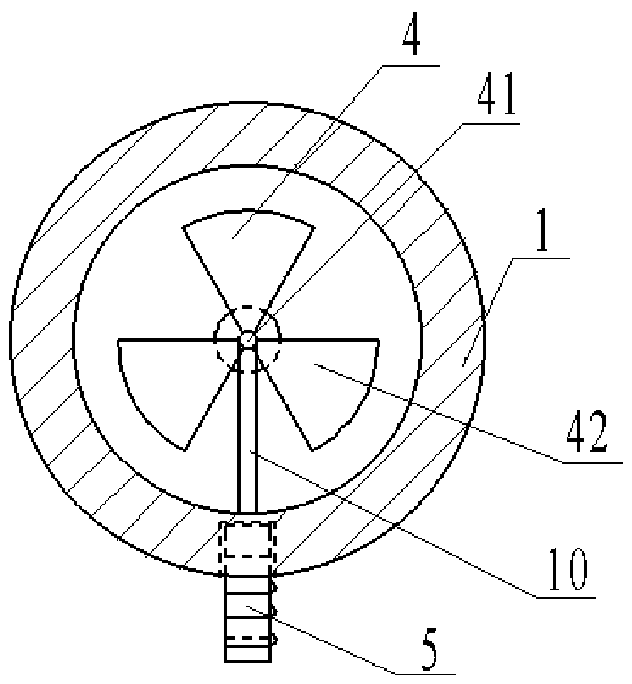
[0060] as attached figure 2 As shown, it also includes a gas filling pipe 1, a valve 2, a motor 31 and a motor bracket 32. The valve 2 is made up of a valve knob 21 , a valve flap 22 and a valve shaft 23 , and the valve knob 21 and the valve flap 22 are welded on the valve shaft 23 . The installation direction of the valve rotating shaft 23 is perpendicular to the axial direction of the gas filling pipe 1 , and the valve disc 22 is installed in the gas filling pipe 1 . The valve flap 22 is circular in shape, and its radius is equal to the inner diameter of the gas filling pipe 1 . The motor bracket 32 is welded on the outer wall surface of the gas filling pipe 1, and the motor 31 is installed on the motor bracket 32; the motor 31 is installed vertically with the valve shaft 23, and can drive the valve shaft 23 to rotate (for detailed installation steps of the motor, please refer to the prior art) . When the valve knob 21 i...
PUM
 Abstract
Description
Claims
Application Information
 - R&D
- Intellectual Property
- Life Sciences
- Materials
- Tech Scout
- Unparalleled Data Quality
- Higher Quality Content
- 60% Fewer Hallucinations
Browse by: Latest US Patents, China's latest patents, Technical Efficacy Thesaurus, Application Domain, Technology Topic, Popular Technical Reports.
© 2025 PatSnap. All rights reserved.Legal|Privacy policy|Modern Slavery Act Transparency Statement|Sitemap|About US| Contact US: help@patsnap.com


