
Wavelet denoising method for partial discharge of DC gas-insulated electrical equipment

A technology for partial discharge and electrical equipment, applied in the field of partial discharge wavelet denoising of DC gas-insulated electrical equipment, can solve the problems of increasing signal standardization, re-sampling, complex calculation process, inapplicability, etc., to improve the risk factor evaluation and simple calculation , the effect of improving detection accuracy and accuracy

Active Publication Date: 2020-04-21
杭州国洲电力科技有限公司
View PDF6 Cites 2 Cited by
  • Summary
  • Abstract
  • Description
  • Claims
  • Application Information

AI Technical Summary

Problems solved by technology

Wavelet denoising technology has been applied to the partial discharge denoising of AC electrical equipment. However, the mechanisms of AC partial discharge and DC partial discharge are different. The wavelet denoising technology of AC partial discharge is not suitable for DC partial discharge denoising. Discharge wavelet denoising technology is still in the initial stage of research
Moreover, the traditional optimal wavelet selection is based on the correlation coefficient method. In order to overcome the problem of different lengths between the partial discharge signal and the wavelet function, this method needs to add steps such as signal standardization, resampling, and displacement, and the calculation process is complex and time-consuming.

Method used


Image

  • Wavelet denoising method for partial discharge of DC gas-insulated electrical equipment
  • Wavelet denoising method for partial discharge of DC gas-insulated electrical equipment
  • Wavelet denoising method for partial discharge of DC gas-insulated electrical equipment

Examples


Embodiment Construction

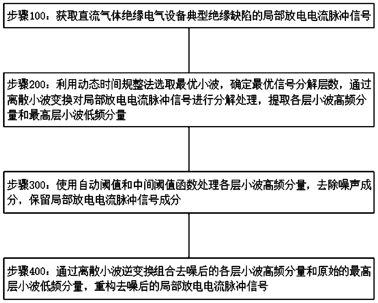
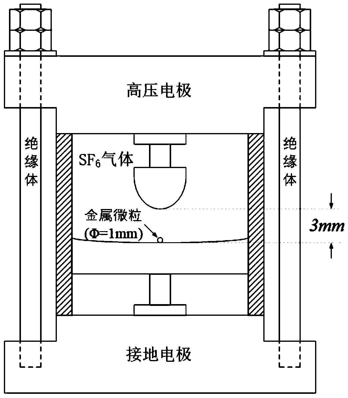
[0039] refer to Figure 1 to Figure 8 A partial discharge wavelet denoising method for DC gas-insulated electrical equipment is shown, which includes steps:

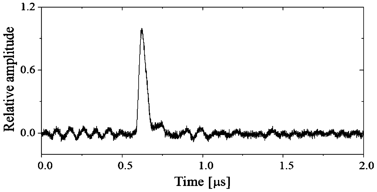
[0040] Step 1): Obtain partial discharge current pulse signals of typical insulation defects of DC gas-insulated electrical equipment;

[0041] Step 2): Using the dynamic time warping method to select the optimal wavelet, determine the optimal number of signal decomposition layers, decompose the partial discharge current pulse signal through discrete wavelet transform, and extract the wavelet high frequency components of each layer and the highest wavelet low frequency component;

[0042] Step 3): use automatic threshold and intermediate threshold functions to process wavelet high-frequency components of each layer, remove noise components, and retain partial discharge current pulse signal components;

[0043] Step 4): Combining the denoised wavelet high-frequency components of each layer and the original highest-level ...


PUM


Abstract

The invention discloses a wavelet denoising method for partial discharge of DC gas-insulated electrical equipment. The wavelet denoising method comprises the following steps of: (1) acquiring partialdischarge current pulse signals of a typical insulation defect of the DC gas-insulated electrical equipment; (2) selecting an optimal wavelet by using a dynamic time warping method, determining an optimal signal decomposition layer number, carrying out decomposition processing on the partial discharge current pulse signal through discrete wavelet transform, and extracting a wavelet high-frequencycomponent of each layer and a wavelet low-frequency component of the highest layer; (3) processing the wavelet high-frequency components of each layer by using automatic threshold value and intermediate threshold value functions, removing noise components, and reserving partial discharge current pulse signal components; and (4) combining the denoised wavelet high-frequency component of each layerand the original wavelet low-frequency component of the highest layer through inverse discrete wavelet transform, and reconstructing a denoised partial discharge current pulse signal. The wavelet denoising method effectively removes interference in direct-current partial discharge, improves the detection precision and precision, is simple and rapid in calculation, and is easy to implement.

Description

technical field [0001] The invention relates to a wavelet denoising method for partial discharge of DC gas-insulated electrical equipment. Background technique [0002] The rapid development of HVDC power transmission and distribution technology puts forward higher requirements for the safety and stability of related DC gas-insulated electrical equipment. The partial discharge generated at the insulation defect of DC gas-insulated electrical equipment leads to the gradual deterioration of the insulation system of the equipment, which in turn causes secondary accidents such as equipment failure, fire, and casualties. Therefore, detection of partial discharge is an important means for on-line monitoring, risk assessment and asset management of DC gas-insulated electrical equipment, and it is also an effective method to ensure the safe and stable operation of electrical equipment and the entire power system. However, in the on-site partial discharge detection process, white no...

Claims


Application Information

Patent Timeline
IPC IPC(8): G01R31/12G06K9/00
CPCG01R31/1227G06F2218/06
Inventor 王国明沈佳华汤敏刘德茂胡晗
Owner 杭州国洲电力科技有限公司
Learn More