
Tire recycling and cutting device

A cutting device and tire technology, applied in the direction of plastic recycling, recycling technology, etc., can solve the problems of labor-intensive, labor-intensive, and low-efficiency tire skin cutting, and achieve a stable cutting effect

Active Publication Date: 2020-04-21
北京朋米科技有限公司
View PDF7 Cites 13 Cited by
  • Summary
  • Abstract
  • Description
  • Claims
  • Application Information

AI Technical Summary

Problems solved by technology

[0003] People cut scrapped car tires, and the cut tires can be used to make tire soles. Usually, the worker controls the knife with both hands to rotate slowly in the middle of one side of the tire. The knife rotates with the tire skin to cut out The shape of the tire is circular, so that the worker completes the work of cutting the tire skin. In this way, it takes a lot of effort for the worker to cut the tire skin by holding the knife with both hands, and it is more efficient for the worker to use the knife to manually cut the tire skin Low

Method used


Image

  • Tire recycling and cutting device
  • Tire recycling and cutting device
  • Tire recycling and cutting device

Examples


Embodiment 1

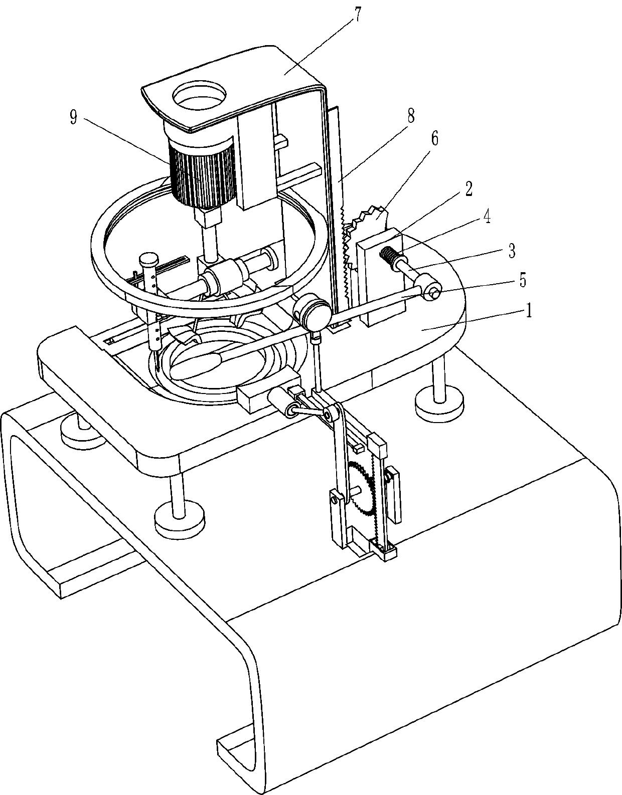
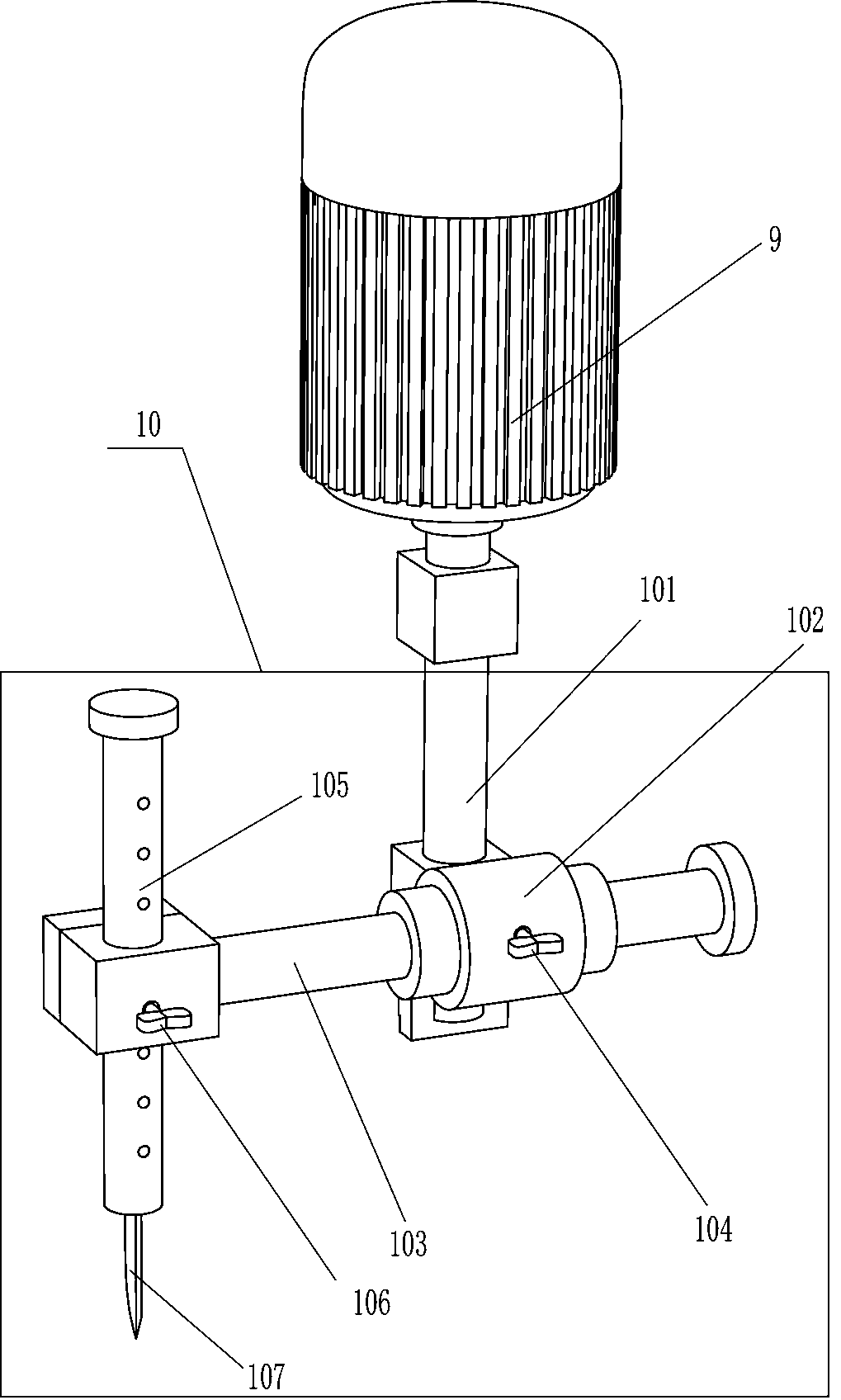
[0022] A tire recycling cutting device, such as Figure 1-3 As shown, it includes a support 1, a roller 201, a first support plate 2, a first rotating rod 3, a first return spring 4, a first swinging rod 5, a sector gear 6, a slide plate 7, a first rack 8, and a motor 9 and the cutting device 10, the upper left side of the workbench is provided with a support 1, the left part of the support 1 is embedded with a rotating drum 201, the upper side rear of the support 1 is provided with a slide plate 7, and the inside top of the slide plate 7 is installed There is a motor 9, the output shaft of the motor 9 is provided with a cutting device 10, the right part of the rear side of the slide plate 7 is provided with a first rack 8, and the support 1 on the rear side of the slide plate 7 is symmetrically provided with a first support plate 2. The upper part of the first support plate 2 on the left and right sides is rotatably provided with the first rotating rod 3, and the first rotati...

Embodiment 2

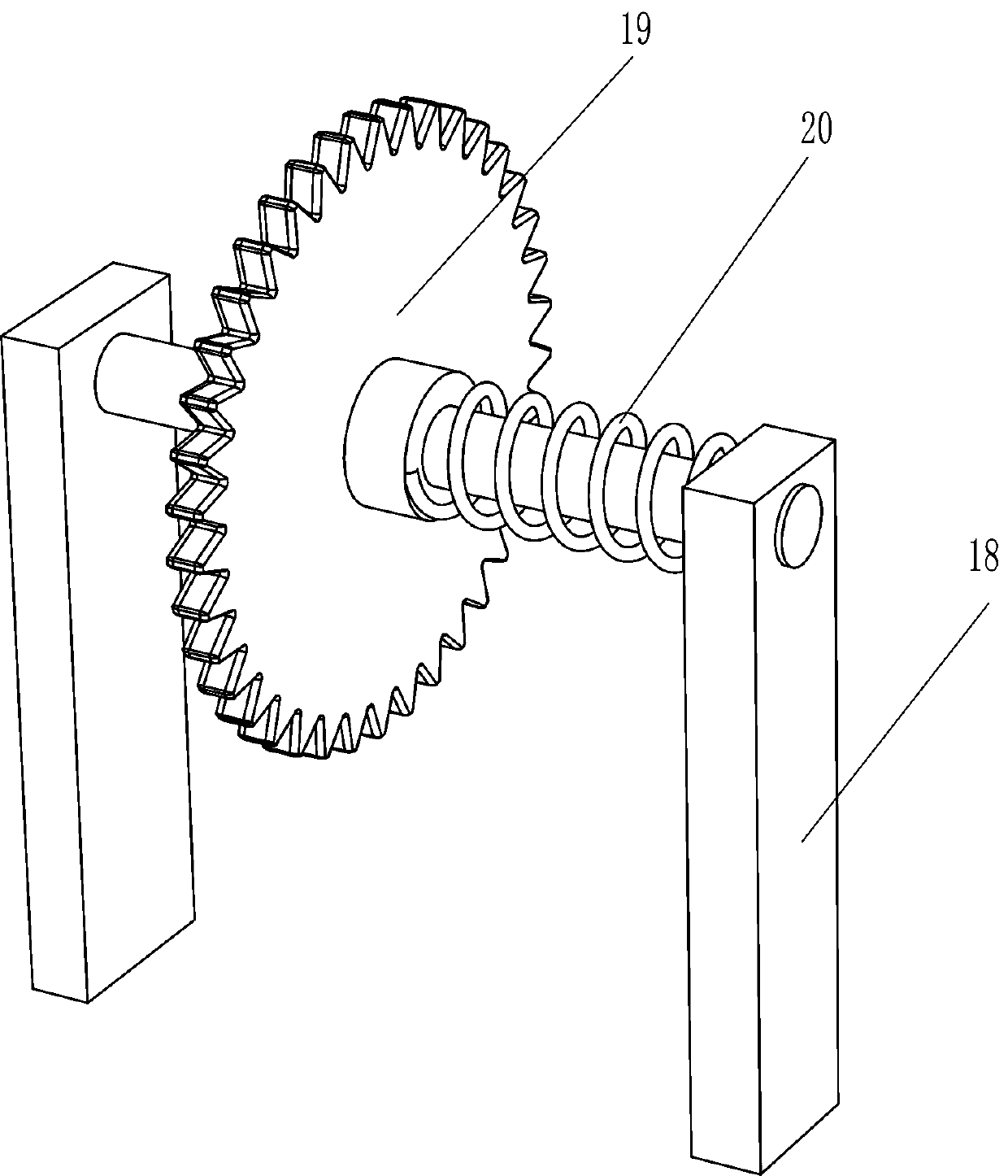
[0027] On the basis of Example 1, such as Figure 4-7 As shown, it also includes a fixed seat 11, a shaft sleeve 111, a second swing lever 12 and a second spring 13, the bottom end of the rotating shaft 101 is provided with a fixed seat 11, and the bottom of the fixed seat 11 is provided with a shaft sleeve 111, and the shaft sleeve 111 A second swing lever 12 is provided on the left side of the front and rear symmetrical rotation type, and a second spring 13 is arranged between the second swing lever 12 inner sides on the front and rear sides.

[0028]Also comprise annular slide rail 14, annular slide block 15, hollow slide bar 16 and pin bar 17, slide plate 7 inboard middle part is provided with annular slide rail 14, is provided with annular slide block 15 slidingly on annular slide rail 14, and annular slide block 15 is provided with a hollow slide bar 16, and the hollow slide bar 16 is slidably provided with a pin bar 17, and the bottom end of the pin bar 17 is connected ...


PUM


Abstract

The invention relates to a cutting device, in particular to a tire recycling and cutting device. The technical problem is how to provide the tire recycling and cutting device capable of automaticallyrotating and cutting and automatically pushing out a cut tire. The tire recycling and cutting device comprises a support, a roller and the like, wherein the roller is embedded into one side of the support in a rotating manner. The tire recycling and cutting device can drive a cutter to rotate to cut a waste tire by means of a cutting device, meanwhile, can adjust the position of the cutter to cutwaste tires with different diameters and different thicknesses, presses the waste tire by using a second swing rod in the process that the cutter moves downwards to pierce the waste tire, so that thewaste tire can be fixed to avoid sliding in the process of piercing and cutting the waste tire, thus the cutting is better completed, and can push away the cut waste tire without manual operation by swinging a first swing rod upwards.

Description

technical field [0001] The invention relates to a cutting device, in particular to a tire recovery cutting device. Background technique [0002] Tires are circular elastic rubber products that are rolled on the ground and rolled on various vehicles or machinery. Usually installed on metal rims, it can support the body, buffer external impact, realize contact with the road surface and ensure the driving performance of the vehicle. Tires are often used under complex and harsh conditions, and they are subjected to various deformations, loads, forces, and high and low temperature effects during driving, so they must have high load-bearing performance, traction performance, and cushioning performance. At the same time, it is also required to have high wear resistance and flex resistance, as well as low rolling resistance and heat generation. Half of the world's rubber consumption is used for tire production, which shows the ability of tires to consume rubber. [0003] People c...

Claims


Application Information

Patent Timeline
Patent Type & Authority Applications(China)
IPC IPC(8): B29B17/04
CPCB29B17/04B29B2017/044Y02W30/62
Inventor 不公告发明人
Owner 北京朋米科技有限公司
Learn More