
Cutting device for corrugated cardboard production line

A corrugated cardboard and cutting device technology, which is applied in metal processing and other directions, can solve problems such as collapse, foaming, degumming, and corrugation, and achieve the effects of stable cutting, stable cutting, and stable production

Active Publication Date: 2021-07-13
杭州永晶科技有限公司
View PDF7 Cites 0 Cited by
  • Summary
  • Abstract
  • Description
  • Claims
  • Application Information

AI Technical Summary

Problems solved by technology

At this time, the end of the corrugated cardboard located at the front side of the cross-cutting machine continues to feed, which is easy to deform the corrugated board after being squeezed, and the phenomenon of inverted corrugated board, collapsed corrugated board, high and low corrugated board, and local foaming and degumming after compounding

Method used


Image

  • Cutting device for corrugated cardboard production line
  • Cutting device for corrugated cardboard production line
  • Cutting device for corrugated cardboard production line

Examples


Embodiment 1

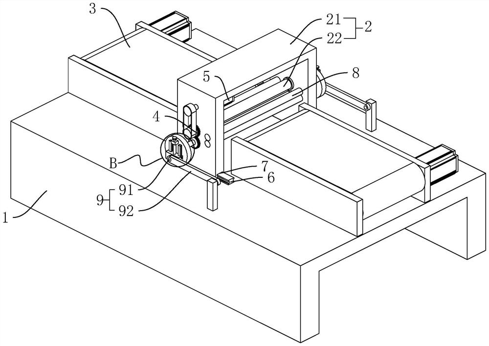
[0040] A cutting device for a corrugated cardboard production line, which is used to be installed between the slitting machine and the stacker of the corrugated cardboard production line, so that the corrugated cardboard coming out of the slitting machine is first cross-cut by the cutting device and then transported to the stacker for further processing. stack. likefigure 1 As shown, the cutting device includes a frame 1, the upper end of the frame 1 is provided with a cutting assembly 2, and the both sides of the cutting assembly 2 along the conveying direction of the corrugated cardboard are respectively provided with conveyor belts 3, and the corrugated cardboard can be further processed by the conveyor belt 3. delivery.

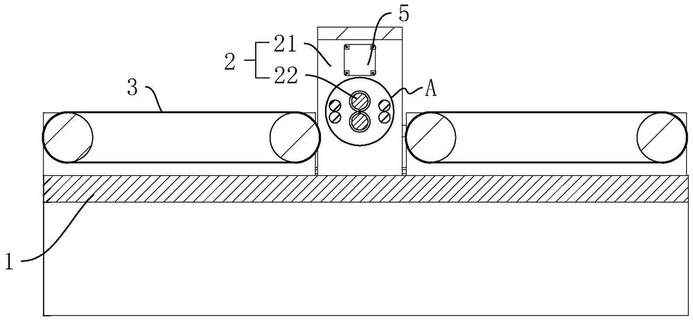
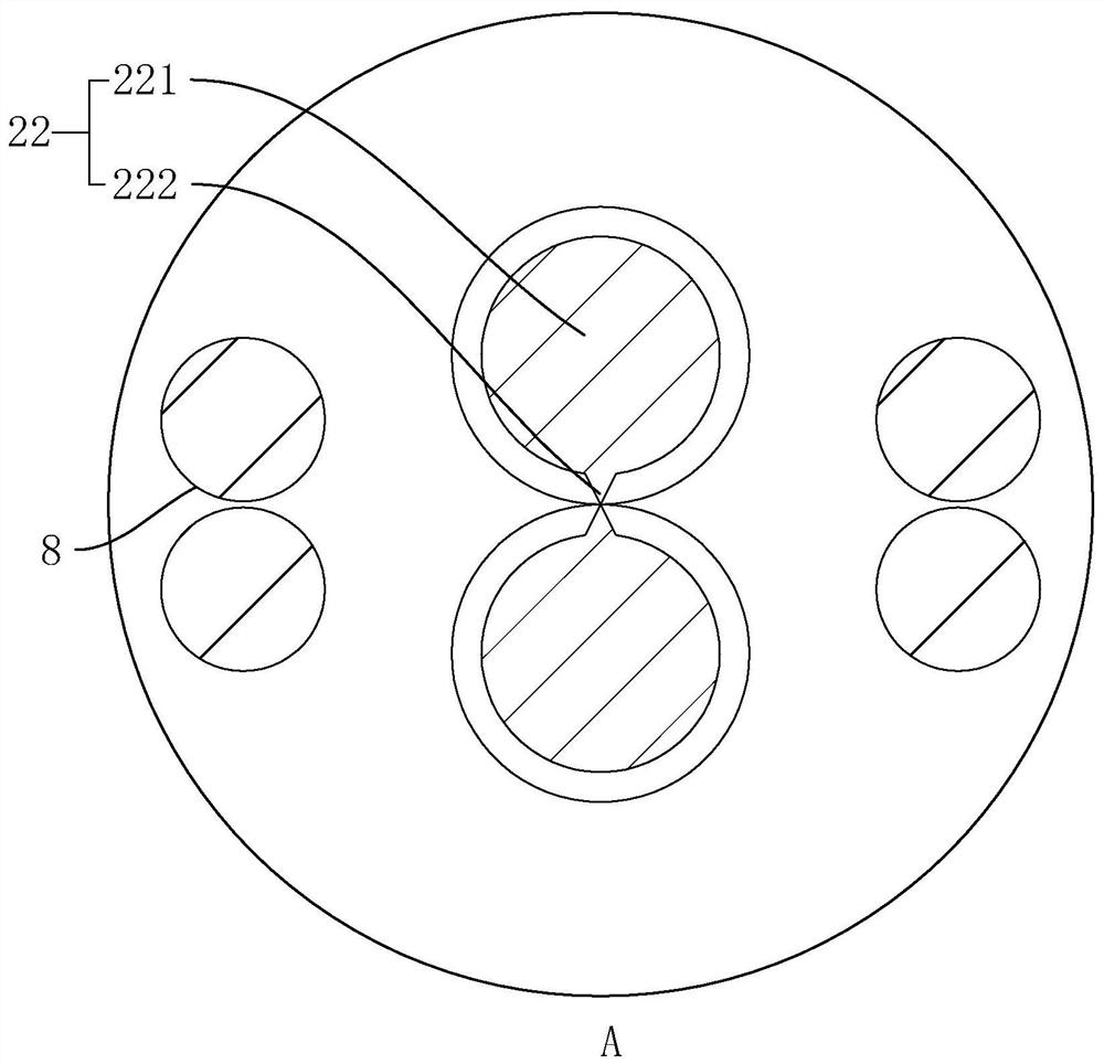
[0041] like figure 2 , image 3 As shown, the cutting assembly 2 includes a mounting frame 21 arranged on the frame 1, and two spiral knives 22 distributed up and down and rotatably connected to the mounting frame 21. The axes of rotation of the two h...

Embodiment 2

[0052] A cutting device for a corrugated cardboard production line, such as Figure 5 As shown, the difference from Embodiment 1 is that the structure of the transmission assembly 9 is different. Each transmission assembly 9 includes a mounting plate 93 fixedly arranged on the frame 1, two horizontal and opposite racks 94 arranged on the mounting plate 93, coaxially fixed on one of the rotating rollers 221 and connected to the two Rack 94 fits incomplete teeth 95 . The incomplete tooth 95 includes a rotating part 951 fixedly connected to the axial end of the rotating roller 221, and a plurality of tooth parts 952 fixed on the outer wall of the rotating part 951. Just after the upper rack 94 is disengaged, the tooth portion 952 is also just opened and engaged with the lower rack 94 . In actual use, the rotating part 951 of the incomplete tooth 95 is in the shape of a disc, and the diameter of the rotating part 951 can also be selected to be smaller, so that the reciprocating ...


PUM


Abstract

The invention discloses a cutting device for a corrugated cardboard production line, which relates to the field of corrugated cardboard production. It includes a frame on which a cutting assembly is arranged, and the cutting assembly includes a mounting frame that is slidably connected to the frame along the corrugated cardboard conveying direction. , two spiral knives distributed up and down and rotatably connected to the mounting frame, each spiral knife includes a rotating roller rotatably connected to the mounting frame, a cutting edge arranged on the outer wall of the rotating roller along the axial direction of the rotating roller, and the rotating roller Gears are fixed at one end of the axial direction, and the two helical knives rotate synchronously through the meshing of the two gears. A driving motor is also provided on the mounting frame; a transmission assembly is also provided on the frame, and the transmission assembly is connected to one of the helical knives and passes through the helical The rotation of the knife drives the mounting frame to move back and forth along the conveying direction of the corrugated cardboard. The transmission assembly is set, and the spiral knife moves along the conveying direction during cutting, which reduces the extrusion and deformation of the corrugated cardboard on the front side during the cutting process, making the overall production more stable.

Description

technical field [0001] The invention relates to the field of corrugated cardboard production, more specifically, it relates to a cutting device for a corrugated cardboard production line. Background technique [0002] Corrugated cardboard, also known as corrugated cardboard, is made of at least one layer of corrugated cardboard and a layer of boxboard paper (also called boxboard), which has good elasticity and extensibility. Corrugated cardboard production is usually processed through specialized production lines. [0003] Such as the Chinese utility model patent whose patent announcement number is CN206551579U, this patent discloses a kind of corrugated cardboard production system. Including the first single-facer corrugating unit, the second single-facer corrugating unit, the third single-facer corrugating unit, overpass conveying frame, surface paper feeding unit, multiple preheating cylinders, gluing machine, bonding machine, slitting machine, transverse Cutting machin...

Claims


Application Information

Patent Timeline
Patent Type & Authority Patents(China)
IPC IPC(8): B26D1/40B26D7/01B26D7/26
CPCB26D1/40B26D7/015B26D7/2628
Inventor 姚成袁增跃
Owner 杭州永晶科技有限公司
Learn More