
Wire threader for CNC wire cutting machine

A wire threader and cutting machine technology, applied in the field of numerical control, can solve the problems of complicated manual threading operation, high vision requirements, difficult perforation, etc., and achieve the effects of simple and convenient operation, small size and simple structure

Active Publication Date: 2021-11-19
郭光淦
View PDF8 Cites 0 Cited by
  • Summary
  • Abstract
  • Description
  • Claims
  • Application Information

AI Technical Summary

Problems solved by technology

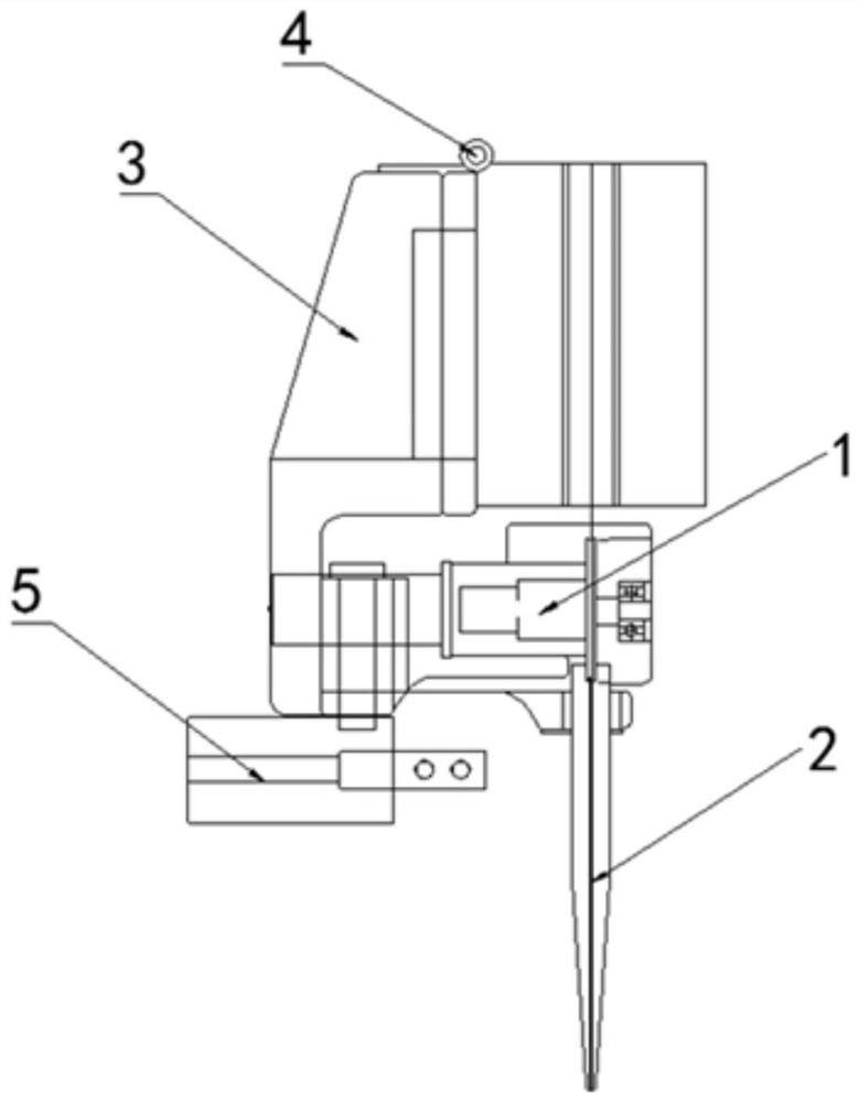
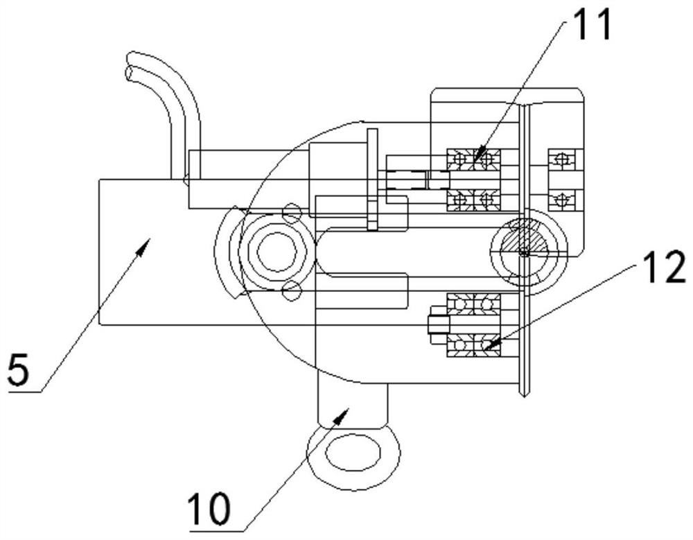
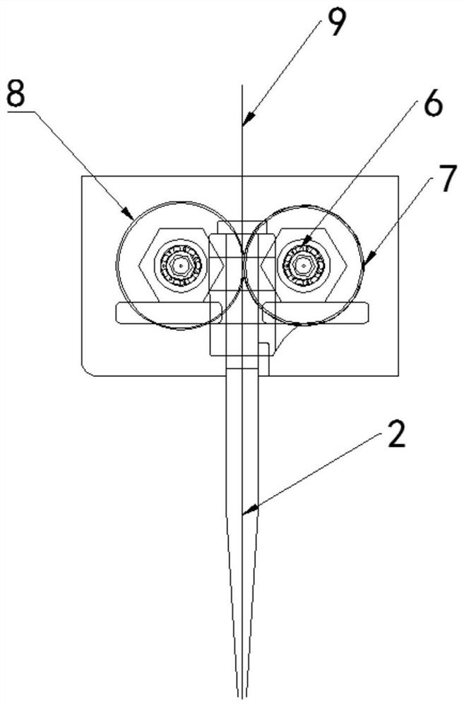
[0004] The purpose of the present invention is to solve the problems of difficult perforation in the prior art, and at the same time, the manual threading operation is complicated, the labor load is large, and the vision requirements are high, so a wire threader for a digitally controlled wire cutting machine is proposed

Method used


Image

  • Wire threader for CNC wire cutting machine
  • Wire threader for CNC wire cutting machine
  • Wire threader for CNC wire cutting machine

Examples


Embodiment Construction

[0021] The following will clearly and completely describe the technical solutions in the embodiments of the present invention with reference to the accompanying drawings in the embodiments of the present invention. Obviously, the described embodiments are only some, not all, embodiments of the present invention.

[0022] In describing the present invention, it should be understood that the terms "upper", "lower", "front", "rear", "left", "right", "top", "bottom", "inner", " The orientation or positional relationship indicated by "outside", etc. is based on the orientation or positional relationship shown in the drawings, and is only for the convenience of describing the present invention and simplifying the description, rather than indicating or implying that the referred device or element must have a specific orientation, so as to Specific orientation configurations and operations, therefore, are not to be construed as limitations on the invention.

[0023] refer to Figure ...


PUM


Abstract

The invention relates to a wire threader of a digitally controlled wire cutting machine, belonging to the technical field of numerically controlled. The wire threader includes a support seat, a wire guide nozzle, a pin shaft and a finger cylinder. A hinge plate is installed in the support seat. The hinge plate includes a first hinge plate and a second hinge plate. The first hinge plate is welded to the support seat. The hinge plate is movably connected with the support seat through the pin shaft. The end faces of the first hinge plate and the second hinge plate are provided with semicircular countersunk holes, and the guide wire nozzle is nested in the semicircular countersink holes. There are bearing seat holes on each of the bearing seat holes, guide wheels are installed on the bearing seat holes, rotating bolts are arranged on the side of the threader, and finger cylinders are arranged on the back of the threader; The structure of the wire device is simple, and the operation is simple and convenient through the finger cylinder or bolt control. Shields are installed on the driving guide wheel and the driven guide wheel, which is not easy to cause the molybdenum wire to slip off, which solves the problem that the molybdenum wire is soft and difficult to thread, and saves threading. time, improving work efficiency.

Description

technical field [0001] The invention relates to the technical field of numerical control, in particular to a wire threader of a numerical control wire cutting machine. Background technique [0002] Wire cutting machine tool belongs to the category of electrical processing. Wire cutting machine was also invented in the former Soviet Union in 1960. Its basic physical principle is that free positive ions and electrons accumulate in the field and quickly form an ionized conductive channel. Wire cutting machine tool is made of When the Lazarinko couple in the former Soviet Union studied the phenomenon and causes of the damage of the switch contacts by spark discharge corrosion, they found that the instantaneous high temperature of the electric spark could melt and oxidize the local metal and be corroded, thus creating and inventing the electric discharge machining method , at this stage, a current is formed between the two plates, resulting in countless collisions between the par...

Claims


Application Information

Patent Timeline
Patent Type & Authority Patents(China)
IPC IPC(8): B23H7/10
CPCB23H7/102
Inventor 郭光淦
Owner 郭光淦
Learn More