
Low bend loss optical fiber with a chlorine doped core and offset trench

A core, fiber technology, applied in the direction of multi-layer core/clad fiber, graded index core/clad fiber, clad fiber, etc., can solve the problem of low microbending loss, difficult macrobending loss, low Cable cut-off wavelength and other issues

Active Publication Date: 2020-04-17
CORNING INC
View PDF8 Cites 3 Cited by
  • Summary
  • Abstract
  • Description
  • Claims
  • Application Information

AI Technical Summary

Problems solved by technology

In some fiber designs, it is difficult to simultaneously achieve low macrobend loss, low microbend loss, low cable cutoff wavelength, zero dispersion wavelength between 1300nm and 1324nm, 1310 mode field diameter of 8.2 to 9.6 microns and compliance with ITU G.652 / G.657 standard

Method used


Image

  • Low bend loss optical fiber with a chlorine doped core and offset trench
  • Low bend loss optical fiber with a chlorine doped core and offset trench
  • Low bend loss optical fiber with a chlorine doped core and offset trench

Examples


Embodiment approach A

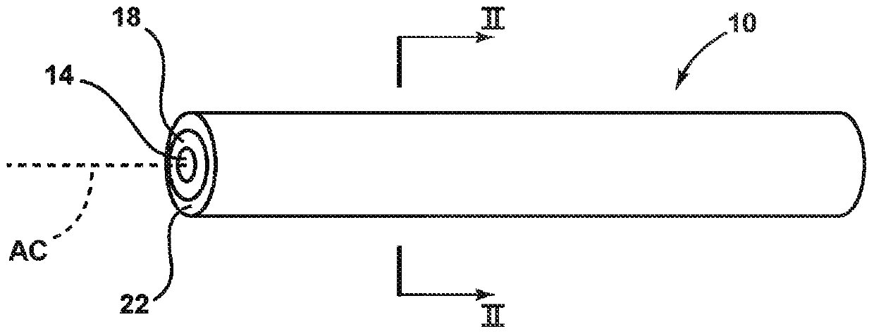
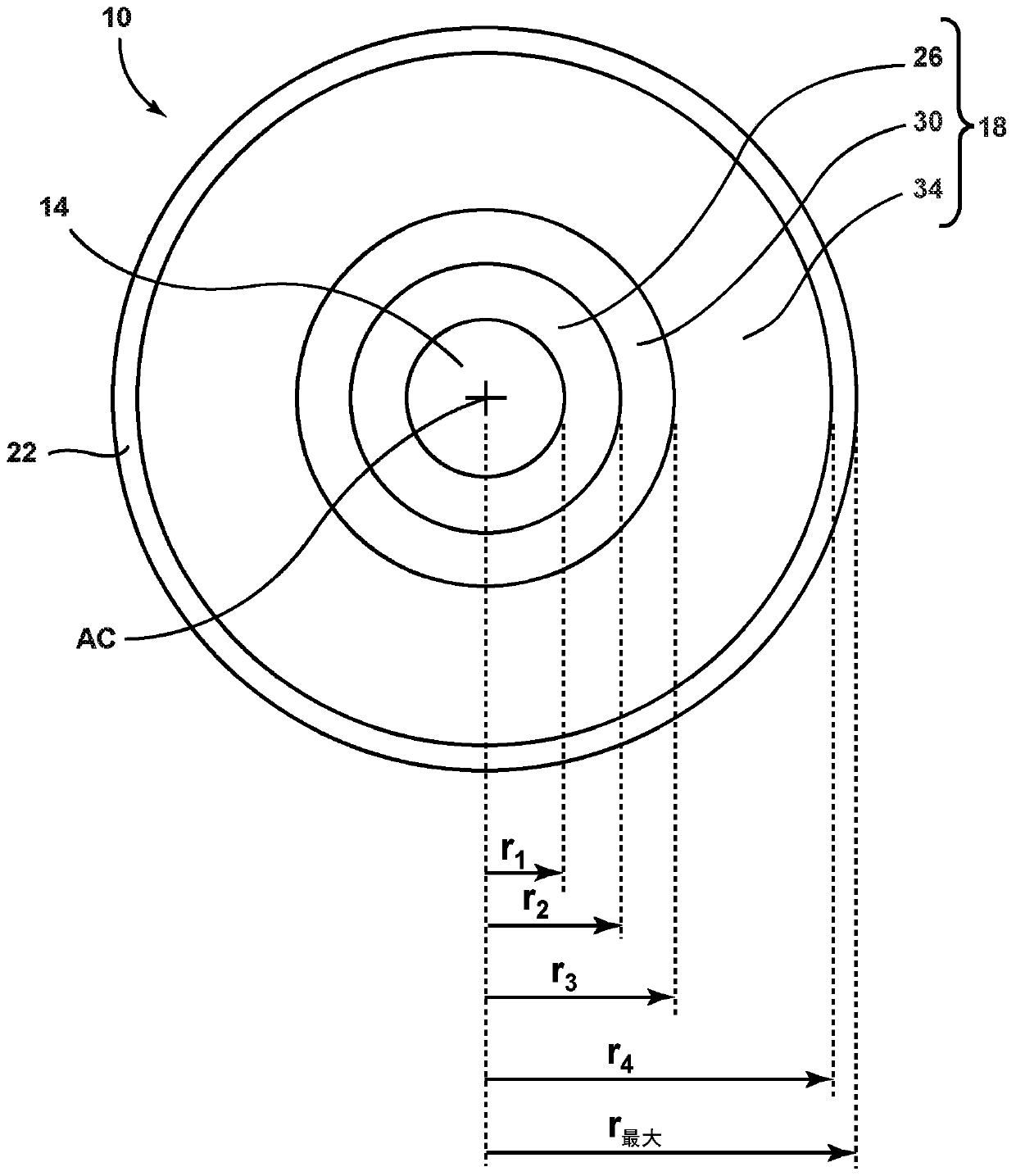
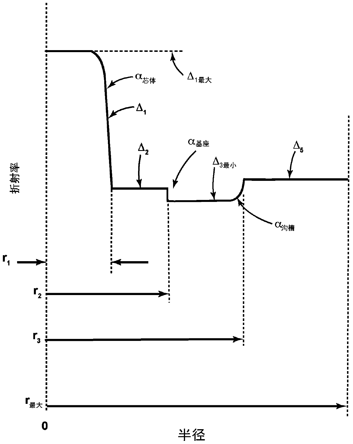
[0120] Embodiment A is a single-mode optical fiber comprising: (i) a chlorine-doped silica-based core comprising a core alpha (core α )≥4, radius r 1 and the maximum refractive index delta Δ 1最大 (ii) a cladding surrounding the core, said cladding comprising: a. a first inner cladding region adjacent to and in contact with the core and having a refractive index delta Δ 2 , radius r 2 and the minimum refractive index delta Δ 2最小 , so that Δ 2最小 1最大 and b. an outer cladding region surrounding the second inner cladding region and having a refractive index Δ 5 and radius r 最大 , so that Δ 2最小 ≥Δ 5 . The mode field diameter MFD of the optical fiber at 1310 is ≥ 9 microns, the cable cut-off is ≤ 1260 nm, and the zero dispersion wavelength range is 1300 nm ≤ λ 0 ≤1324nm, and for a 20mm mandrel, the macrobending loss at 1550nm is less than 0.75dB / turn.

[0121] The single-mode optical fiber of Embodiment A, further comprising a second inner cladding adjacent to and in contact ...

Embodiment approach B

[0130] Embodiment B is a single-mode optical fiber comprising: (i) a chlorine-doped silica-based core comprising a core alpha (core α )≥4, radius r 1 and the maximum refractive index delta Δ 1最大 (ii) a cladding surrounding the core, said cladding comprising: a. a first inner cladding region adjacent to and in contact with the core and having a refractive index delta Δ 2 , radius r 2 and the minimum refractive index delta Δ 2最小 , so that Δ 2最小 1最大 ; b. a second inner cladding adjacent to and in contact with the first inner cladding and having a refractive index Δ 3 , radius r 3 and the maximum refractive index delta Δ 3最大 , so that Δ 2最小 3最大 and c. an outer cladding region surrounding the second inner cladding region and having a refractive index Δ 5 and radius r 最大 , so that Δ 5 3最大 . The mode field diameter MFD of the optical fiber at 1310 is ≥ 9 microns, the cable cut-off is ≤ 1260 nm, and the zero dispersion wavelength range is 1300 nm ≤ λ 0 ≤1324nm, and for a 2...


PUM

PropertyMeasurementUnit
Outer radiusaaaaaaaaaa

Abstract

An optical fiber includes (i) a chlorine doped silica based core having a core alpha (Core alpha) >=4, a radius r1, and a maximum refractive index delta 1max % and (ii) a cladding surrounding the core. The cladding surrounding the core includes a) a first inner cladding region adjacent to and in contact with the core and having a refractive index delta 2, a radius r2, and a minimum refractive index delta 2min such that delta 2min < delta 1max, b) a second inner cladding adjacent to and in contact with the first inner cladding having a refractive index delta 3, a radius r3, and a minimum refractive index delta 3min such that 3min < delta 2, and c) an outer cladding region surrounding the second inner cladding region and having a refractive index delta5, a radius rmax, and a minimum refractive index delta 3min such that delta 3min < delta 2.

Description

[0001] This application claims the benefit of priority under 35 U.S.C. §119 to U.S. Provisional Application Serial No. 62 / 542,518, filed August 8, 2017, and Dutch Patent Application No. 2019817, filed October 27, 2017, filed as The contents of both are based on and are incorporated by reference in their entirety. technical field [0002] The present disclosure relates generally to single-mode optical fibers having low bend loss, in particular to optical fibers having a chlorine-doped core, and more particularly to single-mode optical fibers having a chlorine-doped core and a cladding surrounding the core with the cladding having offset trench regions optical fiber. Background technique [0003] There is a need for optical fibers with low bending losses, especially for use in so-called "access" and fiber-to-the-premises (FTTx) optical networks. Optical fibers may be deployed in such networks in such a way that they cause bending losses in the optical signals transmitted thro...

Claims


Application Information

Patent Timeline
IPC IPC(8): G02B6/028G02B6/036
CPCG02B6/03633G02B6/03644G02B6/0365G02B6/0286
Inventor D·C·布克班德李明军S·K·米什拉P·坦登
Owner CORNING INC
Learn More