
Monitoring-facilitating power distribution cabinet

A technology for power distribution cabinets and cabinets, which is applied in the field of power distribution cabinets that are easy to monitor. It can solve the problems of dust entering, easily endangering the personal safety of staff, and increasing the labor intensity of staff, so as to achieve the effect of easy cleaning

Active Publication Date: 2020-04-17
WUHU INST OF TECH
View PDF3 Cites 2 Cited by
  • Summary
  • Abstract
  • Description
  • Claims
  • Application Information

AI Technical Summary

Problems solved by technology

[0003] Most of the existing enterprises and residential buildings use traditional meter-type power distribution cabinets for power distribution. The voltage and current of this kind of power distribution cabinets are displayed by pointer instruments, and the staff need to go to the site to check the power distribution data regularly, which enhances the staff's confidence. Labor intensity; In addition, the staff need to open the cabinet door to observe the current, voltage and operating conditions during daily inspection or maintenance operations. After the cabinet door is opened, it is easy to allow external dust to enter the power distribution cabinet, affecting the work of various components, and All conductive parts behind the cabinet door are directly exposed in front of the staff, which is likely to endanger the personal safety of the staff

Method used


Image

  • Monitoring-facilitating power distribution cabinet
  • Monitoring-facilitating power distribution cabinet
  • Monitoring-facilitating power distribution cabinet

Examples


Embodiment Construction

[0023] In order to make the object, technical solution and advantages of the present invention clearer, the present invention will be described in further detail below in conjunction with specific embodiments and with reference to the accompanying drawings.

[0024] It should be noted that all expressions using "first" and "second" in the embodiments of the present invention are to distinguish two entities with the same name but different parameters or parameters that are not the same, see "first" and "second" It is only for the convenience of expression, and should not be construed as a limitation on the embodiments of the present invention, which will not be described one by one in the subsequent embodiments.

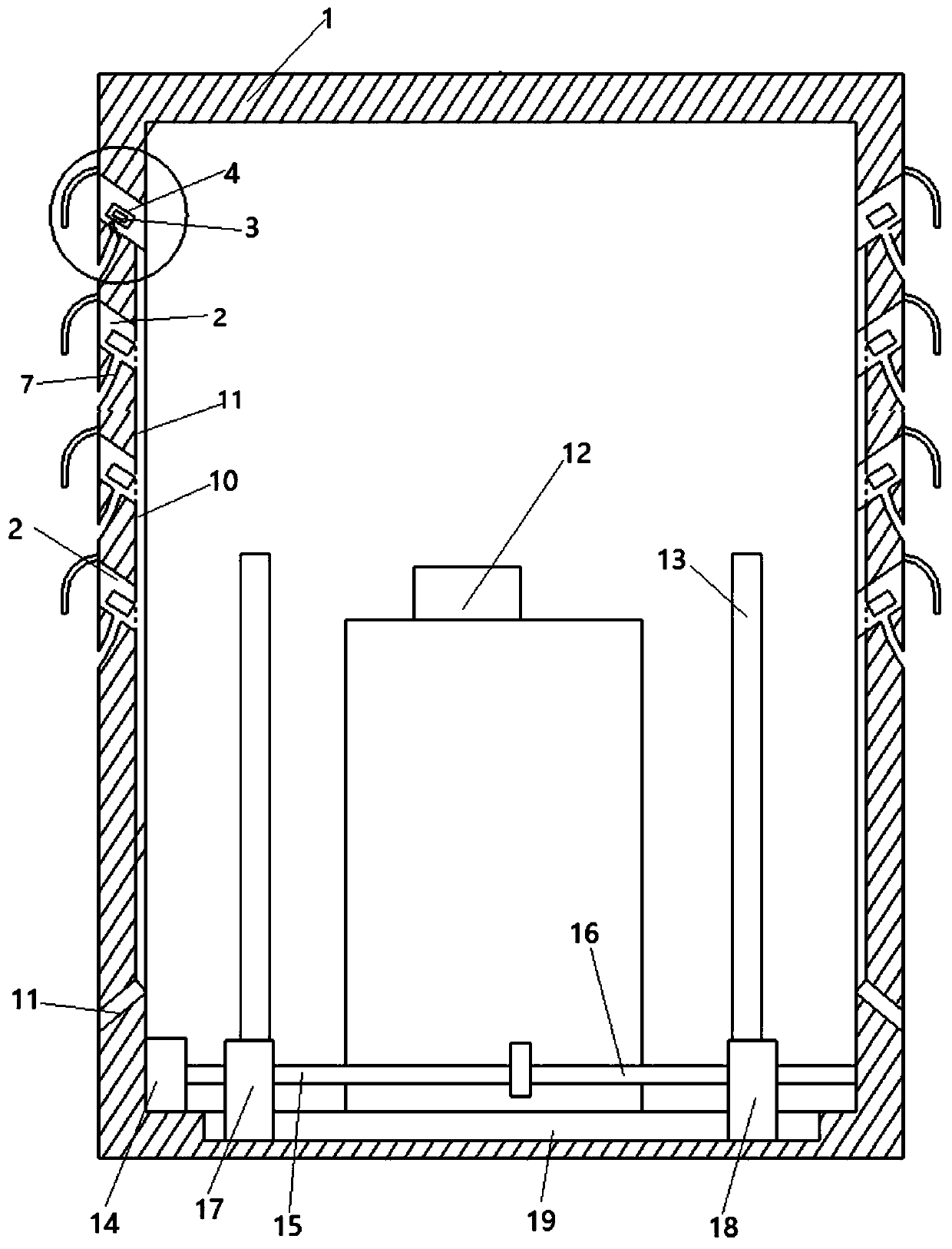
[0025] A power distribution cabinet that is convenient for monitoring, including a power distribution box 1, a diffused air duct 2 is opened on the side wall of the power distribution box 1, and the diffused air duct 2 includes a The air inlet on the wall and the air ...


PUM


Abstract

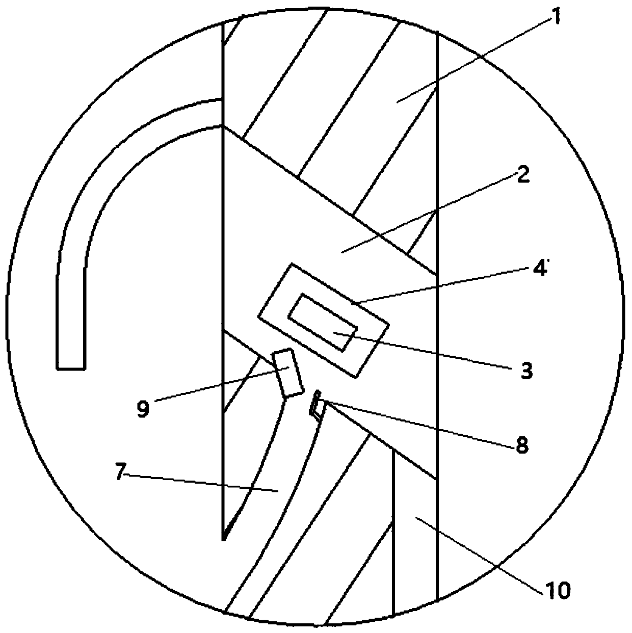
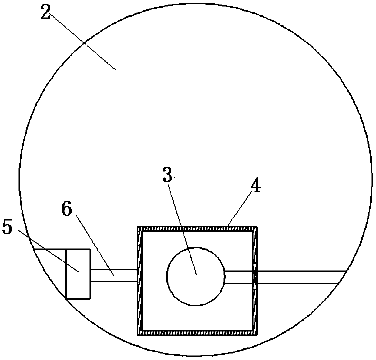
The invention discloses a monitoring-facilitating power distribution cabinet comprising a power distribution box. The side wall of the power distribution box is provided with an air dispersing pipe. The air dispersing pipe comprises an air inlet formed in the inner side wall of the power distribution box and an air outlet formed in the outer side wall of the power distribution box; the height of the air inlet is less than that of the air outlet, a rotating assembly is arranged on the side wall of the air dispersing pipe, a camera is connected to the rotating assembly, a cleaning assembly is arranged on the lower side wall of the air dispersing pipe, and the cleaning assembly is used for cleaning the camera when the rotating assembly drives the camera to rotate downwards. The camera is convenient for remote operation and maintenance personnel to observe the state in the box, some dust is accumulated on the camera for a long time, and the rotating assembly drives the camera to rotate atthe moment so that the camera is moved to the cleaning assembly, the cleaning assembly is enabled to clean the camera and the camera is enabled to monitor the power distribution cabinet.

Description

technical field [0001] The invention relates to the technical field of power distribution cabinets, in particular to a power distribution cabinet that is convenient for monitoring. Background technique [0002] The power distribution cabinet is the final equipment of the power distribution system. The power distribution cabinet is a general term for the motor control center. The power distribution cabinet is used in the occasions where the load is relatively scattered and there are few circuits; the motor control center is used in the occasions where the load is concentrated and there are many circuits. They distribute the electric energy of a certain circuit of the upper-level power distribution equipment to the nearest load. This level of equipment shall provide protection, monitoring and control of the load. [0003] Most of the existing enterprises and residential buildings use traditional meter-type power distribution cabinets for power distribution. The voltage and ...

Claims


Application Information

Patent Timeline
Patent Type & Authority Applications(China)
IPC IPC(8): H02B1/32H02B1/48H02B1/56H02B1/06B08B1/00B08B15/04
CPCH02B1/48H02B1/32H02B1/565H02B1/06B08B1/00B08B15/04B08B1/10Y02E10/50
Inventor 胡明许普乐张俊季双双周舒莹
Owner WUHU INST OF TECH
Learn More