


Quick Research
Generate reliable direction feasibility study reports for your R&D in just a few steps.

Technical Q&A
Discover and master advanced knowledge NOW. Basics, ideas, possibilities, all at once.

Find Solutions
As an expert in R&D theories, this can generate solutions to your technical problems instantly.

Evaluate Feasibility
Analyze your overall solution with one click, know your potential R&D risks in advance.

Monitor Landscape
Get weekly tech updates, stay abreast of the latest tech innovations and key insights.
A kind of coil bracket device for installation of floor heating pipeline
A coil bracket and pipeline installation technology, which is applied in the direction of transportation and packaging, thin material handling, and delivery of filamentous materials, can solve the problems of easy loss of support for water pipes, inability to tighten water pipes, inconvenient transportation and storage, etc., to achieve convenience The effect of winding speed, wide application range, easy disassembly and maintenance
- Summary
- Abstract
- Description
- Claims
- Application Information
AI Technical Summary
Problems solved by technology
Method used
Image


Examples
Embodiment 1
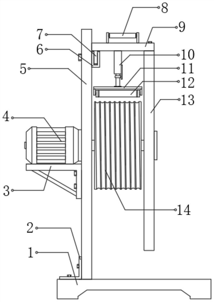
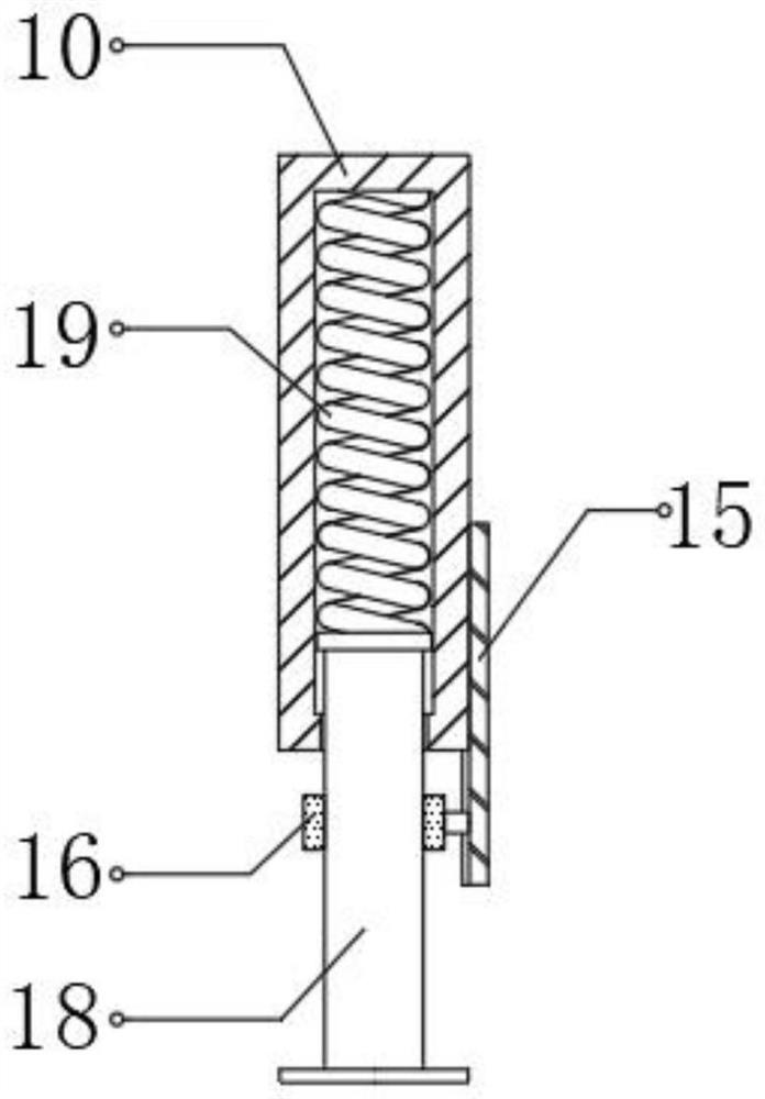
[0027] refer to Figure 1-3 , a coil bracket device for installing a floor heating pipeline, comprising a base 1, a support plate 5 is fixedly connected to one side of the top of the base 1, and an angle iron 2 is connected to the bottom of one side of the support plate 5 by bolts, and the angle iron 2 is connected by bolts It is fixedly connected with the base 1, and one side of the top of the support plate 5 is fixedly connected with the top plate 9, and the middle position of the bottom of the top plate 9 is fixedly connected with a plug 10, and the bottom of the plug 10 is inserted with a plug 18. The bottom is rotatably connected with the roller 12, and a spring 19 is arranged inside the inserting cylinder 10, the bottom of the spring 19 is fixedly connected with the top of the inserting rod 18, and the bottom of one side of the inserting cylinder 10 is welded with a connecting plate 15. The bottom of the side is fixedly connected with the limit ring 16, and the limit rin...
Embodiment 2
[0034] refer to Figure 4 , a coil bracket device for installing a floor heating pipeline. Compared with Embodiment 1, the top of the base 1 near the winding roller 14 is fixedly connected to the speed-limiting block 22, and the middle position of the top of the speed-limiting block 22 is threaded A screw 21 is connected, the top of the screw 21 is fixedly connected with a handle 20, the bottom of the screw 21 is rotatably connected with an arc plate 23 through a bearing, and a rubber pad is adhered to the inner wall of the bottom of the arc plate 23.
[0035] Working principle: During the winding process, one end of the water pipe passes through the interior of the speed limiter block 22, and the screw 21 is screwed down through the turning handle 20, so that the arc plate 23 presses the water pipe downward, increasing the friction during the movement of the water pipe resistance, it is convenient to adjust the winding speed of the water pipe, so that the application range of...
PUM
 Abstract
Description
Claims
Application Information
 - R&D Engineer
- R&D Manager
- IP Professional
- Industry Leading Data Capabilities
- Powerful AI technology
- Patent DNA Extraction
Browse by: Latest US Patents, China's latest patents, Technical Efficacy Thesaurus, Application Domain, Technology Topic, Popular Technical Reports.
© 2024 PatSnap. All rights reserved.Legal|Privacy policy|Modern Slavery Act Transparency Statement|Sitemap|About US| Contact US: help@patsnap.com