Closed roller lead screw mechanism assembling method
A technology of roller screw and assembly method, applied in assembly machines, metal processing, metal processing equipment, etc., can solve the problems of slow assembly speed and poor assembly accuracy, and achieve consistency guarantee, assembly accuracy improvement, and consistency guarantee Effect
- Summary
- Abstract
- Description
- Claims
- Application Information
AI Technical Summary
Problems solved by technology
Method used
Image
Examples
Embodiment 1
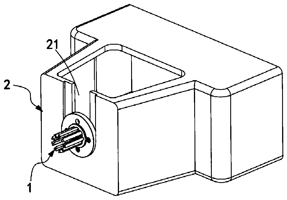
[0056] like Figure 1 to Figure 7 As shown, a closed roller screw mechanism assembly method includes the following steps:
[0057] Step 1, tooling assembly, the auxiliary assembler 1 is installed on the vertical assembly platform 2, the end of the auxiliary assembler 1 is far away from the assembly platform 2, and a number of circumferential arrays are arranged around the axis of the auxiliary assembler 1 An assembly groove 11 arranged vertically, and a through assembly opening 21 is provided on the assembly platform 2 facing the position where the auxiliary assembler 1 is installed;
[0058] Step 2: Install the rollers, insert the rollers 31 one by one in the assembly groove 11 at any time, and screw the first rollers 31 corresponding to the rollers 31 on the end of the auxiliary assembler 1 close to the assembly platform 2. Fastener 12;
[0059] Step 3, pre-positioning the rollers, installing a ring-shaped assembly locator 4 on the end of the auxiliary assembler 1 away fro...
Embodiment 2
[0070] Figure 8 It is a schematic flow diagram of a method of Embodiment 2 of an assembly method of a closed roller screw mechanism of the present invention; Figure 8 As shown, the components that are the same as or corresponding to those in the first embodiment are marked with the corresponding reference numerals in the first embodiment. For the sake of simplicity, only the differences from the first embodiment will be described below. This embodiment two and figure 1 The difference of the shown embodiment one is:
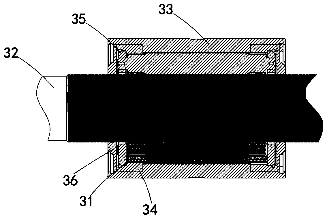
[0071] like Figure 8 and Figure 9 As shown, it also includes step ten, sealing installation, respectively assembling sealing end caps 36 and retaining rings 37 at the openings of the axial ends of the nut 33, and the sealing end caps 36 connecting the rollers 31, teeth Ring 34, limiter 35 and the threaded part of the roller 31 and the screw 32 are sealed in the nut 33, and the retaining ring 37 is against the nut 33 and the sealing end cover 36 between. ...
Embodiment 3
[0075] Figure 10 It is a structural schematic diagram of Embodiment 3 of an assembly method of a closed roller screw mechanism of the present invention; Figure 10 As shown, the parts that are the same as or corresponding to those in the second embodiment are marked with the corresponding reference numerals in the second embodiment. For the sake of simplicity, only the differences from the second embodiment will be described below. This embodiment three and Figure 9 The differences of the illustrated embodiment two are:
[0076] like Figure 10 As shown, the inner ring of the sealing end cap 36 is provided with a threaded portion 361 that is mated with the external thread on the screw rod 32 .
[0077] It should be noted that, in order to improve the sealing performance of the sealing end cap 36, a threaded part 361 that is matched with the external thread of the screw rod 32 is provided on the inner ring of the sealing end cap 36, so that the sealing end cap 36 can be co...
PUM
 Abstract
Description
Claims
Application Information
 - R&D
- Intellectual Property
- Life Sciences
- Materials
- Tech Scout
- Unparalleled Data Quality
- Higher Quality Content
- 60% Fewer Hallucinations
Browse by: Latest US Patents, China's latest patents, Technical Efficacy Thesaurus, Application Domain, Technology Topic, Popular Technical Reports.
© 2025 PatSnap. All rights reserved.Legal|Privacy policy|Modern Slavery Act Transparency Statement|Sitemap|About US| Contact US: help@patsnap.com


