
A dehumidification and heat dissipation device for a power distribution cabinet

A technology of heat dissipation device and power distribution cabinet, which is applied to the substation/distribution device casing, the cooling/ventilation of the substation/switchgear, and the details of the substation/switch arrangement, etc. Fire and other problems, to achieve the effect of high degree of automation, convenient and fast use

Active Publication Date: 2021-02-09
JIANGSU SUZHONG SWITCH FACTORY CO LTD
View PDF6 Cites 0 Cited by
  • Summary
  • Abstract
  • Description
  • Claims
  • Application Information

AI Technical Summary

Problems solved by technology

[0002] The electric cabinet is suitable for lighting, power distribution and control in substations, power plants, industrial and mining enterprises, etc. It has the characteristics of strong breaking current capacity, good dynamic and thermal stability, convenient combination and strong practicability. Devices of electrical equipment such as switches, relays, and instruments are widely used in various types of modern equipment. The existing various power distribution cabinets have defects such as complex structures and cumbersome operations, which are inconvenient to use. In addition, these equipments require a long time Therefore, the need for heat dissipation is more obvious. If the heat gas inside the equipment cannot be dissipated in time, it is likely to burn out the internal components of the equipment, causing many unnecessary losses, and even causing a fire; in addition, the inside of the power distribution cabinet There are a lot of equipment, and it is necessary to dehumidify while dissipating heat to prevent conduction due to excessive moisture

Method used


Image

  • A dehumidification and heat dissipation device for a power distribution cabinet
  • A dehumidification and heat dissipation device for a power distribution cabinet
  • A dehumidification and heat dissipation device for a power distribution cabinet

Examples


Embodiment Construction

[0014] All features disclosed in this specification, or steps in all methods or processes disclosed, may be combined in any manner, except for mutually exclusive features and / or steps.

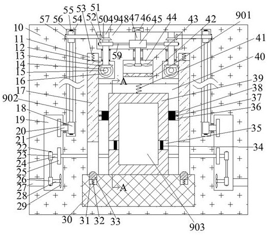
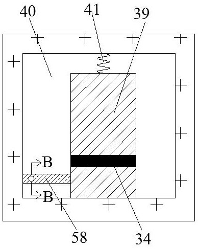
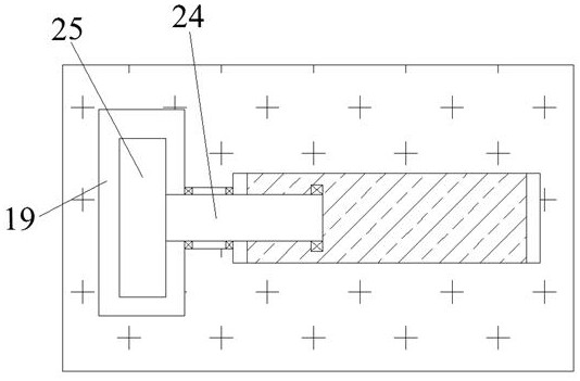
[0015] Combine below Figure 1-Figure 3 The present invention is described in detail, and for convenience of description, the orientations mentioned below are now stipulated as follows: figure 1 The up, down, left, right, front and back directions of the projection relationship itself are the same.

[0016] The invention relates to a dehumidification and heat dissipation device for a power distribution cabinet, which is mainly used for dehumidification and heat dissipation of a power distribution cabinet. The invention will be further described below in conjunction with the drawings of the invention:

[0017] A dehumidification and heat dissipation device for a power distribution cabinet according to the present invention includes a body 10, and a heat dissipation device 901 is arranged insid...


PUM


Abstract

A dehumidification and heat dissipation device for a power distribution cabinet according to the present invention includes a body, a heat dissipation device is provided in the body, a fan is included in the heat dissipation device, and dehumidification devices are also provided on both sides of the heat dissipation device. There is a heat dissipation device to dissipate heat from the distribution box to prevent the overheating of the distribution box from affecting the normal transmission of power. There are dehumidification devices on both sides of the heat dissipation device to dehumidify the bottom of the distribution box to prevent the bottom of the distribution box from being wet for a long time , resulting in damage to the distribution box, or even a short circuit in the power supply. This device has a high degree of automation and is convenient and quick to use.

Description

technical field [0001] The invention relates to the field of dehumidification and heat dissipation of a power distribution cabinet, in particular to a dehumidification and heat dissipation device for a power distribution cabinet. Background technique [0002] The electric cabinet is suitable for lighting, power distribution and control in substations, power plants, industrial and mining enterprises, etc. It has the characteristics of strong breaking current capacity, good dynamic and thermal stability, convenient combination and strong practicability. Devices of electrical equipment such as switches, relays, and instruments are widely used in various types of modern equipment. The existing various power distribution cabinets have defects such as complex structures and cumbersome operations, which are inconvenient to use. In addition, these equipments require a long time Therefore, the need for heat dissipation is more obvious. If the heat gas inside the equipment cannot be d...

Claims


Application Information

Patent Timeline
Patent Type & Authority Patents(China)
IPC IPC(8): H02B1/56H02B1/28
CPCH02B1/28H02B1/565
Inventor 不公告发明人
Owner JIANGSU SUZHONG SWITCH FACTORY CO LTD
Learn More