Plug connector and connector assembly
A technology of plug connectors and connector components, applied in the direction of instruments, optical components, optics, etc., can solve the problems of long overall size of plug connectors, achieve the effects of improving service life, avoiding excessive bending, and improving tensile strength
- Summary
- Abstract
- Description
- Claims
- Application Information
AI Technical Summary
Problems solved by technology
Method used
Image
Examples
Embodiment 1
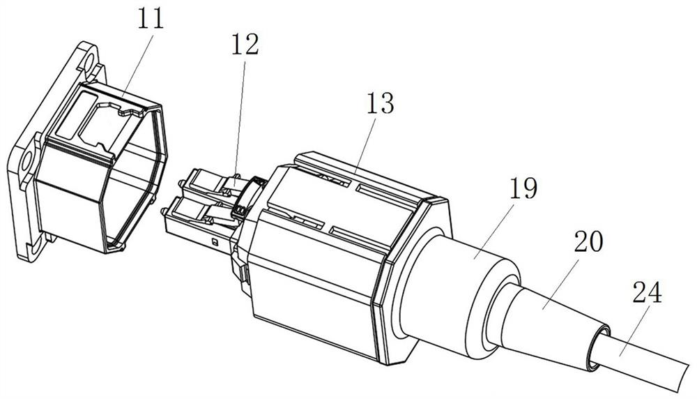
[0056] Such as Figure 3 to Figure 5 As shown, the connector assembly includes a socket connector and a plug connector, with the plug end as the front end, the socket connector includes a socket housing 11, and the inner wall of the socket housing 11 is provided with a protrusion 22, and the protrusion 22 is along the left and right direction There are two in a symmetrical arrangement.
[0057] In this embodiment, the plug connector includes a plug housing 13, and a ferrule 12 is arranged inside the plug housing 13. The ferrule 12 includes a plug 14, a locking shrapnel 15, an unlocking shrapnel 16 and a pull ring 17; the locking shrapnel 15 is set On the upper surface of the plug 14, the rear end of the locking shrapnel 15 is an upturned free end, and the locking shrapnel 15 can lock the plug 14 in the jack of the socket connector; the front end of the unlocking shrapnel 16 is an upturned free end. The free end, the free end of the unlocking elastic piece 16 extends above the...
Embodiment 2
[0070] The difference between this embodiment and Embodiment 1 is that in Embodiment 1, the movable part is an elastic arm 21, and the elastic arm 21 can swing back and forth along the radial direction of the plug housing 13, so that the corresponding slot on the elastic arm 21 25 and the projection 22 snap fit, and then the elastic arm 21 is limited by the limit portion 23 at the front end of the plug housing 13 . And in this embodiment, if Figure 9 As shown, the socket housing 31 is provided with a protrusion 35, the plug housing 32 is provided with a ferrule 33, the ferrule 33 is provided with a sliding hole, the movable part is a slider 34, and the slider 34 can move along the plug housing 32. The radial reciprocating slide of the slider 34 makes the corresponding slot 37 on the slider 34 engaged with the protrusion 35 ; after that, the slider 34 is limited by the stopper 36 at the front end of the plug housing 32 .
Embodiment 3
[0072] The difference between this embodiment and Embodiment 1 is that in Embodiment 1, there are two elastic arms 21, which are respectively arranged on the left and right sides of the ferrule 12, and the elastic arms can swing back and forth along the radial direction of the plug housing 13. , so that the corresponding slot 25 on the elastic arm 21 engages with the protrusion 22 , and then the elastic arm 21 is limited by the limit portion 23 at the front end of the plug housing 13 . And in this embodiment, if Figure 10 and Figure 11 As shown, the socket housing 41 is provided with a protrusion 47, and the plug housing 42 is provided with a ferrule 43. The ferrule 43 includes a locking elastic piece 44, an unlocking elastic piece 45 and an elastic arm 46. The elastic arm 46 is provided with one and integrated Formed on the unlocking spring 45, the outer side of the elastic arm 46 is provided with a card slot 49, and there are three card slots 49 arranged at intervals alon...
PUM
 Abstract
Description
Claims
Application Information
 - R&D
- Intellectual Property
- Life Sciences
- Materials
- Tech Scout
- Unparalleled Data Quality
- Higher Quality Content
- 60% Fewer Hallucinations
Browse by: Latest US Patents, China's latest patents, Technical Efficacy Thesaurus, Application Domain, Technology Topic, Popular Technical Reports.
© 2025 PatSnap. All rights reserved.Legal|Privacy policy|Modern Slavery Act Transparency Statement|Sitemap|About US| Contact US: help@patsnap.com


