CPCI case monitoring method and device

A chassis and remote monitoring technology, applied in hardware monitoring, transmission systems, instruments, etc., can solve the problems that cannot meet the requirements of unattended system applications

Pending Publication Date: 2020-04-14
11TH RES INST OF CHINA ELECTRONICS TECH GROUP CORP
View PDF0 Cites 0 Cited by
  • Summary
  • Abstract
  • Description
  • Claims
  • Application Information

AI Technical Summary

Problems solved by technology

[0003] The embodiment of the present invention provides a CPCI chassis monitoring method and device to solve the problem that the prior art cannot satisfy the application of unattended systems

Method used


Image

  • CPCI case monitoring method and device
  • CPCI case monitoring method and device
  • CPCI case monitoring method and device

Examples


Embodiment Construction

[0046] Exemplary embodiments of the present invention will be described in more detail below with reference to the accompanying drawings. Although exemplary embodiments of the present invention are shown in the drawings, it should be understood that the invention may be embodied in various forms and should not be limited to the embodiments set forth herein. Rather, these embodiments are provided for more thorough understanding of the present invention and to fully convey the scope of the present invention to those skilled in the art.

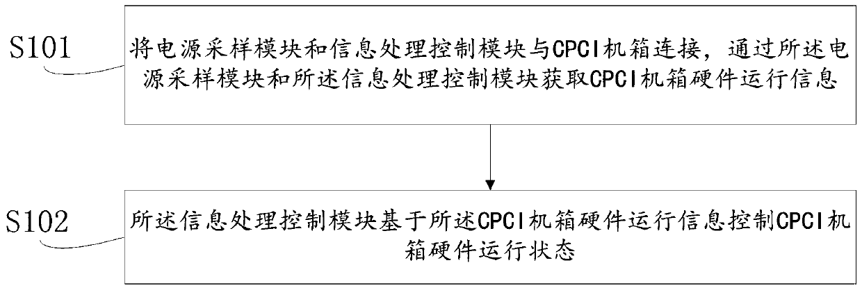
[0047] The first embodiment of the present invention provides a CPCI chassis monitoring method, such as figure 1 As shown, the method includes the following steps:

[0048] S101, connecting the power sampling module and the information processing control module with the CPCI chassis, and obtaining the hardware operation information of the CPCI chassis through the power sampling module and the information processing control module;

[0049]Opti...


PUM


Abstract

The invention discloses a CPCI case monitoring method and device. The method comprises the following steps that a power supply sampling module and an information processing control module are connected with a compact peripheral component interconnection standard CPCI case; the CPCI case hardware operation information is obtained through the power supply sampling module and the information processing control module, and the information processing control module controls the CPCI case hardware operation state based on the CPCI case hardware operation information. The hardware running state can be automatically controlled, and the problem that unattended system application cannot be met in the prior art is solved.

Description

technical field [0001] The invention relates to the field of CPCI (Compact Peripheral Component Interconnect, compact peripheral component interconnection standard) chassis field, in particular to a CPCI chassis monitoring method and device. Background technique [0002] CPCI (Compact Peripheral Component Interconnect) is a bus interface standard proposed by PICMG (PCI Industrial Computer Manufacturer's Group) in 1994. The CPCI chassis is a mechanical box based on the CPCI bus, which has functions such as board installation and fixing, system power supply, and heat dissipation. Widely used in real-time control, industrial automation, real-time data acquisition and other fields. At present, the CPCI chassis adopts local status monitoring and manual local hardware operation status control, which cannot meet the requirements of unattended system applications. Contents of the invention [0003] The embodiments of the present invention provide a method and device for monitori...

Claims


Application Information

Patent Timeline
IPC IPC(8): G06F11/30G06F11/32H04L12/24
CPCG06F11/3055G06F11/3058G06F11/324H04L41/0246
Inventor 邢刚蔡荣宋亚
Owner 11TH RES INST OF CHINA ELECTRONICS TECH GROUP CORP
Why Eureka
Try Eureka