
Combined connecting device for cutting transition section

A technology of connecting device and transition section is applied in the field of combined connecting device for cutting transition section, which can solve the problems of inconvenient installation, inability to adapt to the height of the cutting, and the transition section of the cutting is prone to landslides, etc., and achieves the effect of avoiding landslides.

Inactive Publication Date: 2020-04-14
HUBEI UNIV OF TECH
View PDF1 Cites 0 Cited by
  • Summary
  • Abstract
  • Description
  • Claims
  • Application Information

AI Technical Summary

Problems solved by technology

[0004] Based on the technical problems that the cutting transition section is prone to landslides, the existing device is not easy to install, and cannot adapt to all cutting heights, the present invention proposes a combined connection device for the cutting transition section

Method used


Image

  • Combined connecting device for cutting transition section
  • Combined connecting device for cutting transition section
  • Combined connecting device for cutting transition section

Examples


Embodiment 1

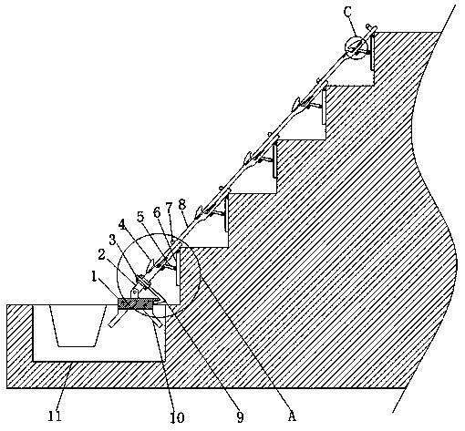
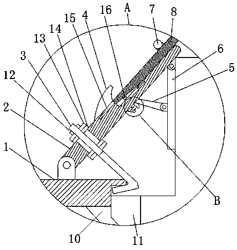
[0028] refer to Figure 1-5 , a combined connection device for road cutting transition section, comprising a base 1, the top of the base 1 is rotatably connected with a first fixed rod 2, the top of the first fixed rod 2 is provided with a first groove, and the first fixed rod 2 is in the first The groove is provided with a second fixed rod 8, and the tops of the first fixed rod 2 and the second fixed rod 8 are rotatably connected with a support plate 6, and one side of the support plate 6 is rotatably connected with two support columns 5, and the two support One end of the column 5 is welded with the same connecting rod 16, and the bottom end of one side of the second fixed rod 8 is provided with an inclined plane opening, and the connecting rod 16 is in the inside of the inclined plane opening, and the top ends of the first fixed rod 2 and the second fixed rod 8 are both The fixed shaft 7 is welded, the fixed shaft 7 is U-shaped, the second fixed rod 8 is between the inner w...

Embodiment 2

[0038] refer to Figure 6 , a combined connection device for road cutting transition sections. Compared with Embodiment 1, in this embodiment, in order to increase the practicability of the device, a chute is provided on the side of the first clamping plate 14 close to the second clamping plate 15, and the second clamping plate 14 is provided with a chute. The side of the plate 15 close to the first clamping plate 14 is welded with a slider, and the slider is matched with the chute. Through the cooperation of the slider and the chute, the first clamping plate 14 and the second clamping plate 15 are not easy to separate, and at the same time, it is convenient to thread The rod 3 passes through the first clamping plate 14 and the second clamping plate 15 at the second circular through hole.

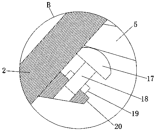
[0039] During use, by rotating the second threaded sleeve 19, the second threaded sleeve 19 makes the threaded column 18 rise, the threaded column 18 drives the support block 17 to rise, th...


PUM


Abstract

The invention belongs to the technical field of roadbed transition sections, and especially relates to a cutting transition section combined connecting device. For the problems that a cutting transition section is easy to slide, an existing device is not convenient to install and cannot be suitable for all cutting heights, the following scheme is completed: the device comprises a base, a first fixing rod is rotationally connected to the top end of the base, a first groove is formed in the top end of the first fixing rod, a second fixing rod is arranged at the position, at the first groove, ofthe first fixing rod, and supporting plates are rotationally connected to the top ends of the first fixing rod and the second fixing rod. A threaded column drives the supporting block to ascend, the supporting block is in contact with a supporting column, the supporting column is rotated to drive the connecting rod to move upwards, the connecting rod enables the second fixing rod to rotate throughthe slope opening of the second fixing rod, then the connecting rod forms a lever through supporting of the fixing shaft and the second fixing rod to apply force to the road cutting, finally the roadcutting is fixed through the supporting plate and the supporting column on the second fixing rod, and landslide is avoided.

Description

technical field [0001] The invention relates to the technical field of roadbed transition sections, in particular to a combined connection device for road cutting transition sections. Background technique [0002] The transition section is mainly to solve the problem of smooth transition between different rigidities and different settlements between adjacent structures in the longitudinal direction of the line. Generally, the steps of the transition section are excavated first, and each layer of filling is filled manually and with bulldozers. However, due to Under the action of the upper part of the subgrade, landslides, cracks and uneven settlement are prone to occur at the interface between the embankment and the cutting. [0003] After retrieval, the Chinese patent application number is CN201620104227.5, which discloses a road slope anti-slide device, including: a supporting main frame, which is fixedly connected with a telescopic support, and the lower part of the suppor...

Claims


Application Information

Patent Timeline
Patent Type & Authority Applications(China)
IPC IPC(8): E01C3/00
CPCE01C3/00
Inventor 汪繁荣孙闯彭禄方娜
Owner HUBEI UNIV OF TECH
Learn More