
S-shaped steel positioning and shaping device

A shaping device and positioning oil cylinder technology, applied in auxiliary devices, forming tools, auxiliary welding equipment, etc., can solve the problems of low production efficiency, difficult welding positioning, high processing costs, etc., to improve efficiency, improve welding accuracy and consistency, The effect of high welding precision

Inactive Publication Date: 2020-04-14
TAIZHOU HAILING HYDRAULIC MACHINERY
View PDF0 Cites 0 Cited by
  • Summary
  • Abstract
  • Description
  • Claims
  • Application Information

AI Technical Summary

Problems solved by technology

The bent S-shaped steel will have elastic deformation, which will bring difficulties to welding positioning
In the prior art, there is a lack of special equipment for welding the S-shaped steel and the horizontal plate together. It can only be manually marked and then fixed with a clamp. Not only the production efficiency is low, but also the welding accuracy is low, the consistency is poor, and the welding deformation is large. Difficulty in follow-up shaping and high processing cost

Method used


Image

  • S-shaped steel positioning and shaping device
  • S-shaped steel positioning and shaping device
  • S-shaped steel positioning and shaping device

Examples


Embodiment Construction

[0020] The present invention will be further described now in conjunction with accompanying drawing.

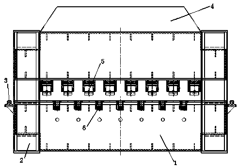
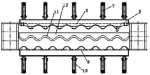
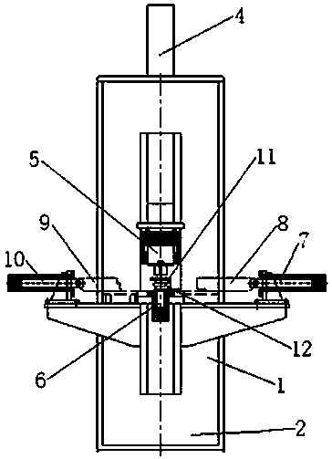
[0021] Such as Figure 1 to Figure 3 As shown, the S-shaped steel S-shaped steel positioning and shaping device includes an upper beam 4 and a lower beam 1 installed on the load-carrying gantry 2, as well as a clamping cylinder 7, a positioning cylinder 10, a pressing cylinder 5 and a shaping cylinder 6.

[0022] The top of lower crossbeam 1 is worktop, and seven shaping oil cylinders 6 are equipped with at equal intervals in the worktop, and the top of shaping oil cylinder 6 is flush with worktop, and shaping oil cylinder 6 is all positioned at the center line of worktop.

[0023] Clamping cylinder 7 and positioning cylinder 10 are arranged symmetrically on both sides of the lower crossbeam 1 working table. There are five clamping cylinders 7 and 10 for positioning. Clamping cylinder 7 is connected with clamping mold 8, and positioning cylinder 10 is connected with positioni...


PUM


Abstract

The invention relates to an S-shaped steel positioning and shaping device. The S-shaped steel positioning and shaping device comprises a workbench and oil cylinders, wherein a lower cross beam is arranged at the lower end of the workbench, the oil cylinders comprise positioning oil cylinders, clamping oil cylinders, pressing oil cylinders and shaping oil cylinders, the positioning oil cylinders are sequentially and fixedly arranged on one side of the top of the lower cross beam, the clamping oil cylinders are fixed to the other side of the top of the lower cross beam in parallel, the positioning oil cylinders, the clamping oil cylinders, the pressing oil cylinders and the shaping oil cylinders are installed at equal intervals, clamping molds, positioning molds, S-shaped steel and a transverse plate are placed on the workbench, the positioning oil cylinders are connected with the positioning molds, the clamping oil cylinders are connected with the clamping molds, the positioning molds and the clamping molds fix the S-shaped steel and the transverse plate from the two sides, the pressing oil cylinders press the top of the S-shaped steel and press the S-shaped steel and the transverseplate on the top of the lower cross beam, and the shaping oil cylinders are located at the bottom of the transverse plate. The S-shaped steel positioning and shaping device is simple in structure, convenient to use, accurate in positioning, high in welding precision, good in consistency, small in welding deformation and convenient to shape, the efficiency is improved, and the cost is reduced.

Description

technical field [0001] The invention relates to a shaped steel fixing device, in particular to an S-shaped steel positioning and shaping device. Background technique [0002] Bridge expansion joints refer to expansion joints usually set between two girder ends, between girder ends and abutments, or at the hinged position of the bridge in order to meet the deformation requirements of the bridge deck. It is required that the expansion joints can freely expand and contract in two directions parallel to and perpendicular to the bridge axis, and are firm and reliable. The vehicles should run smoothly without sudden jumps and noises; they should be able to prevent rainwater and garbage from infiltrating and blocking; installation, inspection, and maintenance , Elimination of dirt should be simple and convenient. Where expansion joints are set, railings and bridge deck pavement must be disconnected. The function of bridge expansion joints is to adjust the displacement and connect...

Claims


Application Information

Patent Timeline
IPC IPC(8): B21D3/00B21D37/04B23K31/00
CPCB21D3/00B23K31/003B23K37/0426B23K37/0443
Inventor 丁克芳
Owner TAIZHOU HAILING HYDRAULIC MACHINERY
Learn More