Motor rotor, reluctance motor and electric vehicle

A technology of motor rotor and rotor core, applied in electric vehicles, motors, electric components, etc., can solve the problems of reducing motor output torque, not easy to saturate, easy to saturate, etc.

Active Publication Date: 2020-04-10
GREE ELECTRIC APPLIANCES INC
View PDF10 Cites 6 Cited by
  • Summary
  • Abstract
  • Description
  • Claims
  • Application Information

AI Technical Summary

Problems solved by technology

At the same time, to increase the output torque of the motor as much as possible, the end of the magnetic steel slot is often bent to increase the pole arc angle. The flux density of the magnetic channel is relatively small, and it is not easy to saturate, which makes the permanent magnet assisted synchronous reluctance motor easy to saturate at the front position of the rotation direction, resulting in serious magnetic flux leakage at the front, reducing the overall output torque of the motor

Method used


Image

  • Motor rotor, reluctance motor and electric vehicle
  • Motor rotor, reluctance motor and electric vehicle
  • Motor rotor, reluctance motor and electric vehicle

Examples


Embodiment Construction

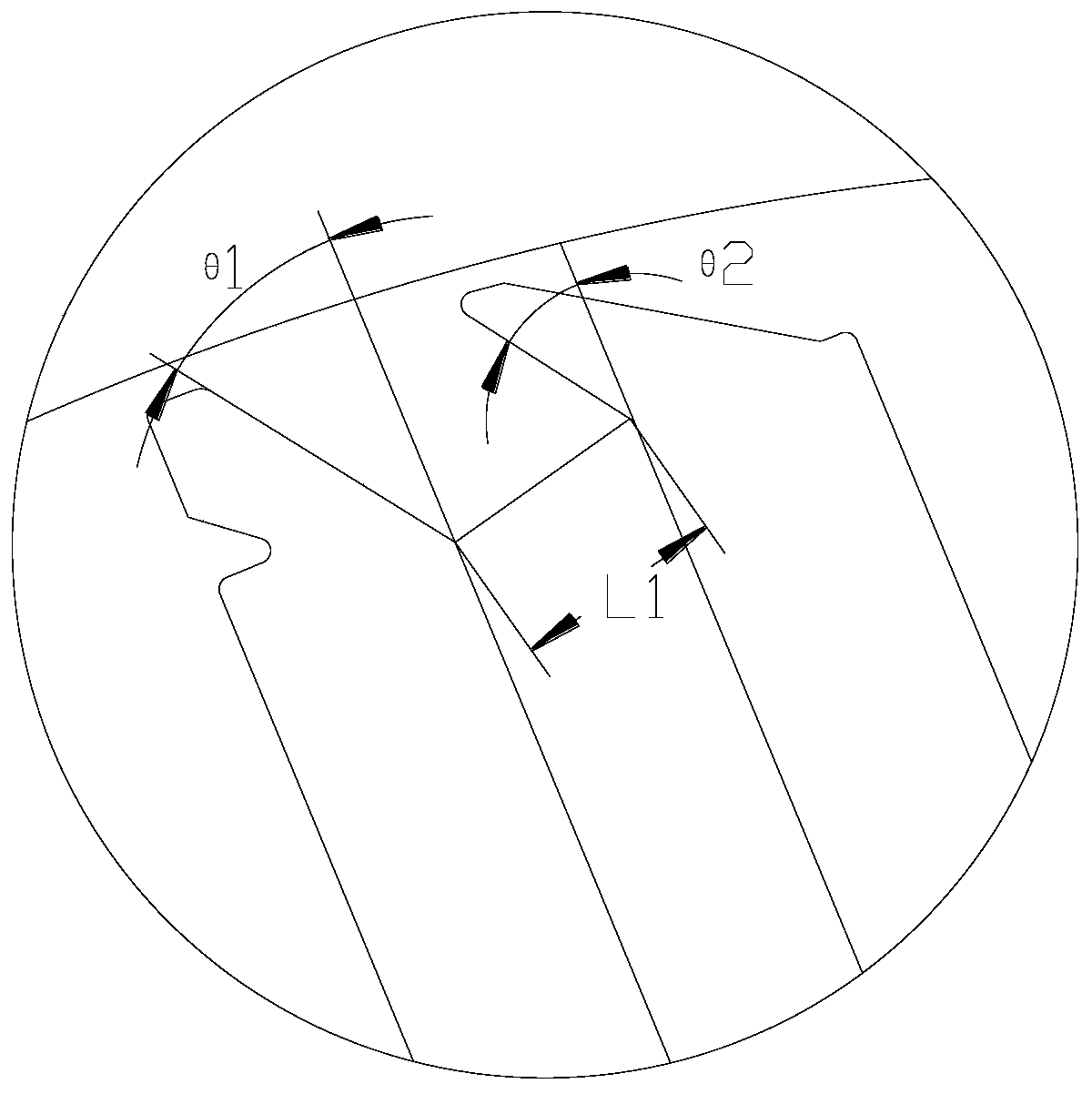
[0029] see in conjunction Figure 1 to Figure 7 As shown, according to the embodiment of the present application, the motor rotor includes a rotor core 1, and the rotor core 1 includes a plurality of magnetic barrier groups arranged in the circumferential direction, and each magnetic barrier group includes at least two magnetic barrier groups arranged at intervals in the radial direction. The magnetic flux barrier 2 forms a magnetic conduction channel 3 between adjacent magnetic flux barriers 2, and a permanent magnet 4 is arranged in the magnetic flux barrier 2. Under the same pole, the radially innermost magnetic flux barrier 2 located at the front edge of the D-axis rotation direction The pole arc angle is ψ, the pole arc angle of the radially innermost flux barrier 2 located at the rear edge of the D-axis rotation direction is ψ1, and the pole arc angle of the radially outermost flux barrier 2 located at the front of the D-axis rotation direction is The angle is ξ, and the...


PUM


Abstract

The invention provides a motor rotor, a reluctance motor and an electric vehicle. The motor rotor comprises a rotor core (1), and the rotor core (1) comprises a plurality of magnetic barrier groups. Each magnetic barrier group comprises at least two magnetic flux barriers (2); magnetic conduction channels (3) are formed between the adjacent magnetic flux barriers (2); permanent magnets (4) are arranged in the magnetic flux barriers (2); and, under the same pole, the pole arc field angle of the flux barrier (2) on the innermost side in the radial direction at the front edge of the D-axis rotation direction is psi; the pole arc opening angle of the radially innermost magnetic flux barrier (2) located at the rear edge of the D-axis rotation direction is psi1, the pole arc opening angle of theradially outermost magnetic flux barrier (2) located at the front edge of the D-axis rotation direction is xi, and the pole arc opening angle of the radially outermost magnetic flux barrier (2) located at the rear edge of the D-axis rotation direction is xi1, wherein psi> psi1, and xi> xi1. According to the motor rotor, the flux density of the leading-edge magnetic conduction channel can be reduced, local magnetic flux leakage is reduced, and the output torque of the motor is improved.

Description

technical field [0001] The present application relates to the technical field of motor equipment, in particular to a motor rotor, a reluctance motor and an electric vehicle. Background technique [0002] With the development of motor technology, in addition to asynchronous motors and rare earth permanent magnet motors, many new motors have emerged in the motor industry. The synchronous reluctance motor uses the principle of minimum reluctance that the magnetic flux always closes along the path of minimum reluctance, and alternately arranges multi-layer magnetic conduction channels and air magnetic barriers in the rotor to form the inductance difference between the d-axis and the q-axis, thereby generating Torque works, but because there is no permanent magnet excitation, it is difficult to control the synchronous reluctance motor, and the motor performance cannot be compared with the rare earth permanent magnet motor. The permanent magnet assisted synchronous reluctance mot...

Claims


Application Information

Patent Timeline
IPC IPC(8): H02K1/27
CPCH02K1/2766H02K2213/03Y02T10/64
Inventor 陈彬王勇廖克亮张健童童
Owner GREE ELECTRIC APPLIANCES INC
Why Eureka
Try Eureka