
Power transmission line operation state monitoring method and device

A technology of power transmission wires and operating status, which is applied in the direction of circuit devices, electrical components, closed-circuit television systems, etc., can solve problems such as difficult vibration measurement, high additional quality, and difficulty in obtaining full-field displacement information, so as to improve accuracy, high precision, The effect of simple structure

Inactive Publication Date: 2020-04-10
HENAN EPRI GAOKE GRP +2
View PDF6 Cites 2 Cited by
  • Summary
  • Abstract
  • Description
  • Claims
  • Application Information

AI Technical Summary

Problems solved by technology

The former needs to select the reference point of displacement zero value, and most of them are point measurements, so it is difficult to obtain the displacement information of the whole field
The latter is based on the acceleration sensor, which needs to integrate the measured acceleration signal to obtain the velocity and displacement, but its additional mass is high. Due to the low frequency and large vibration characteristics of the transmission conductor structure, it is difficult to apply to the vibration measurement of the long and flexible transmission conductor structure. At the same time, in signal processing, due to the low modal frequency of long flexible transmission lines, it is difficult to reduce noise and ensure accuracy

Method used


Image

  • Power transmission line operation state monitoring method and device
  • Power transmission line operation state monitoring method and device

Examples


Embodiment Construction

[0039] The following will clearly and completely describe the technical solutions in the embodiments of the present invention with reference to the accompanying drawings in the embodiments of the present invention. Obviously, the described embodiments are only some of the embodiments of the present invention, not all of them. Based on the embodiments of the present invention, all other embodiments obtained by persons of ordinary skill in the art without making creative efforts belong to the protection scope of the present invention.

[0040] It should be noted that when an element or component is considered to be “connected” to another element or component, it may be directly connected to the other element or component and there may be an intervening element or component at the same time. When an element or component is referred to as being "disposed on" another element or component, it can be directly disposed on the other element or component or intervening elements or compon...


PUM


Abstract

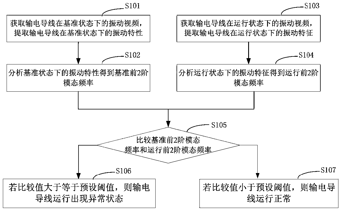
The invention discloses a power transmission wire operation state monitoring method and device, and the method comprises the steps: obtaining a vibration video of a power transmission wire in a reference state, and extracting the vibration characteristics of the power transmission wire in the reference state; analyzing the vibration characteristics in the reference state to obtain the first two-order modal frequency of the reference; acquiring a vibration video of the power transmission wire in an operation state, and extracting vibration characteristics of the power transmission wire in the operation state; analyzing the vibration characteristics in the running state to obtain a second-order modal frequency before running; and comparing the first two-order modal frequency of the referencewith the second-order modal frequency before operation. The method for monitoring the running state of the power transmission wire provided by the invention is simple in structure, high in operability and high in precision, the industrial camera is used for obtaining video information of the benchmark and the running state of the power transmission wire in a non-contact mode, the video information in the benchmark and the video information in the running state are analyzed respectively, noise reduction is conducted, unimportant features are removed, and therefore the monitoring precision is improved.

Description

technical field [0001] The invention relates to the technical field of health monitoring and fault diagnosis of a transmission tower line system structure, in particular to a method and a device for monitoring the running state of a transmission line based on a vibration video of a transmission tower. Background technique [0002] For the structure of long-span transmission tower wires, the structure of long-flexible transmission wires is similar to the dynamic string structure. Under the action of wind load, breeze vibration is very easy to occur, which will cause damage to the tower wire connection structure (clamp structure of the tower wire system, etc.). Fretting fatigue reduces the connection stiffness and the axial tension of the transmission wire, which directly affects the low-order modal frequency characteristics of the long flexible transmission wire. The transmission iron tower is used as the end clamping engineering structure of the transmission wire, and its lo...

Claims


Application Information

Patent Timeline
IPC IPC(8): H02J13/00H04N7/18
CPCH02J13/00H04N7/18
Inventor 张武能汪毅李金峰金俊张帅方堃魏利锋吴克华张留斌王晓晨
Owner HENAN EPRI GAOKE GRP
Learn More