
Compact transformer coil winding robot

A technology of transformer coils and robots, applied in coil manufacturing, inductor/transformer/magnet manufacturing, electrical components, etc., can solve the problems of loose and displaced skeleton, low production efficiency, low product consistency, etc., to prevent the loose and displaced skeleton , Improve production efficiency, fix stable and reliable effect

Inactive Publication Date: 2020-04-10
荆门微田智能科技有限公司
View PDF9 Cites 0 Cited by
  • Summary
  • Abstract
  • Description
  • Claims
  • Application Information

AI Technical Summary

Problems solved by technology

[0001] The patent No. 201811178863.2 proposes a transformer coil winding device, which aims to solve the problem of loosening and shifting of the skeleton due to the lack of effective support of the skeleton during the current transformer coil winding process.
However, it adopts pneumatic expansion and tightening, and its complex structure is difficult to meet the production needs of small-sized coils. The whole machine adopts a horizontal winding method, which requires manual loading and unloading. Before winding, it is necessary to manually fix the wire and the skeleton, and the production efficiency is low. Unable to meet the needs of mass production
Due to the need for manual winding, the product consistency is low, and it is difficult to meet the process requirements of high-precision coil winding

Method used


Image

  • Compact transformer coil winding robot
  • Compact transformer coil winding robot
  • Compact transformer coil winding robot

Examples


Embodiment Construction

[0025] The present invention is further described in conjunction with the following examples.

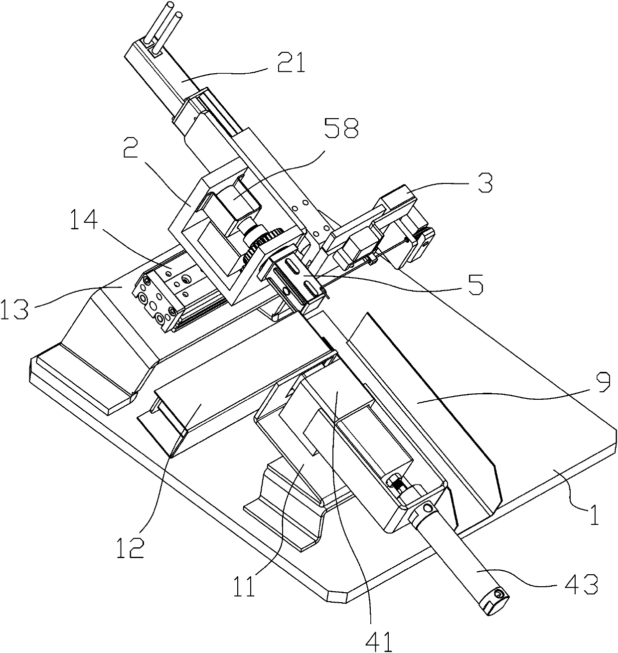
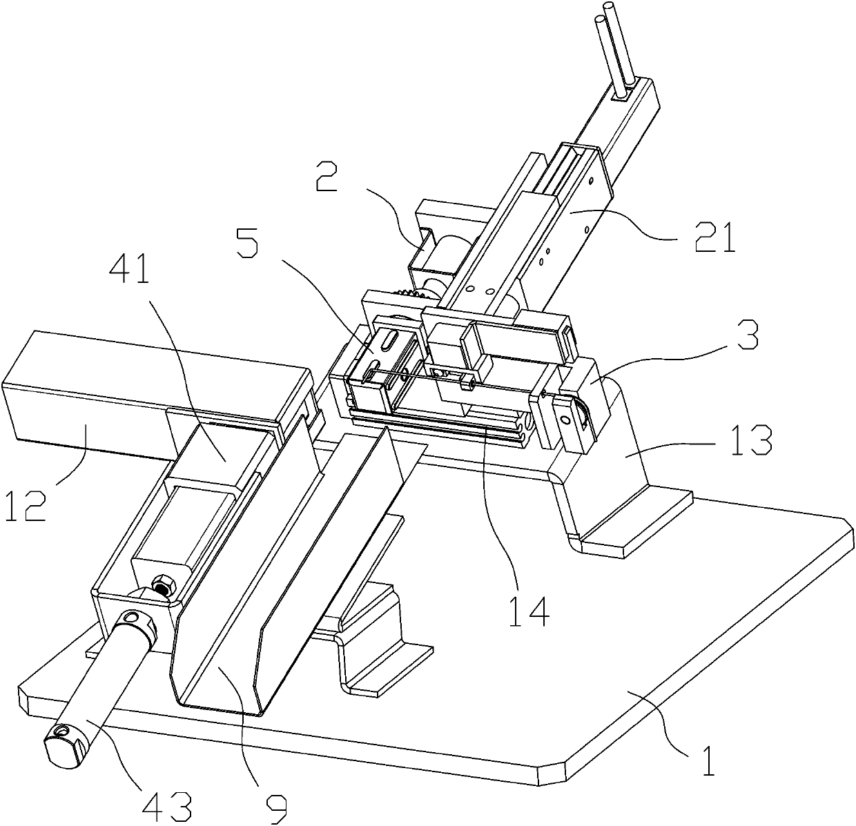
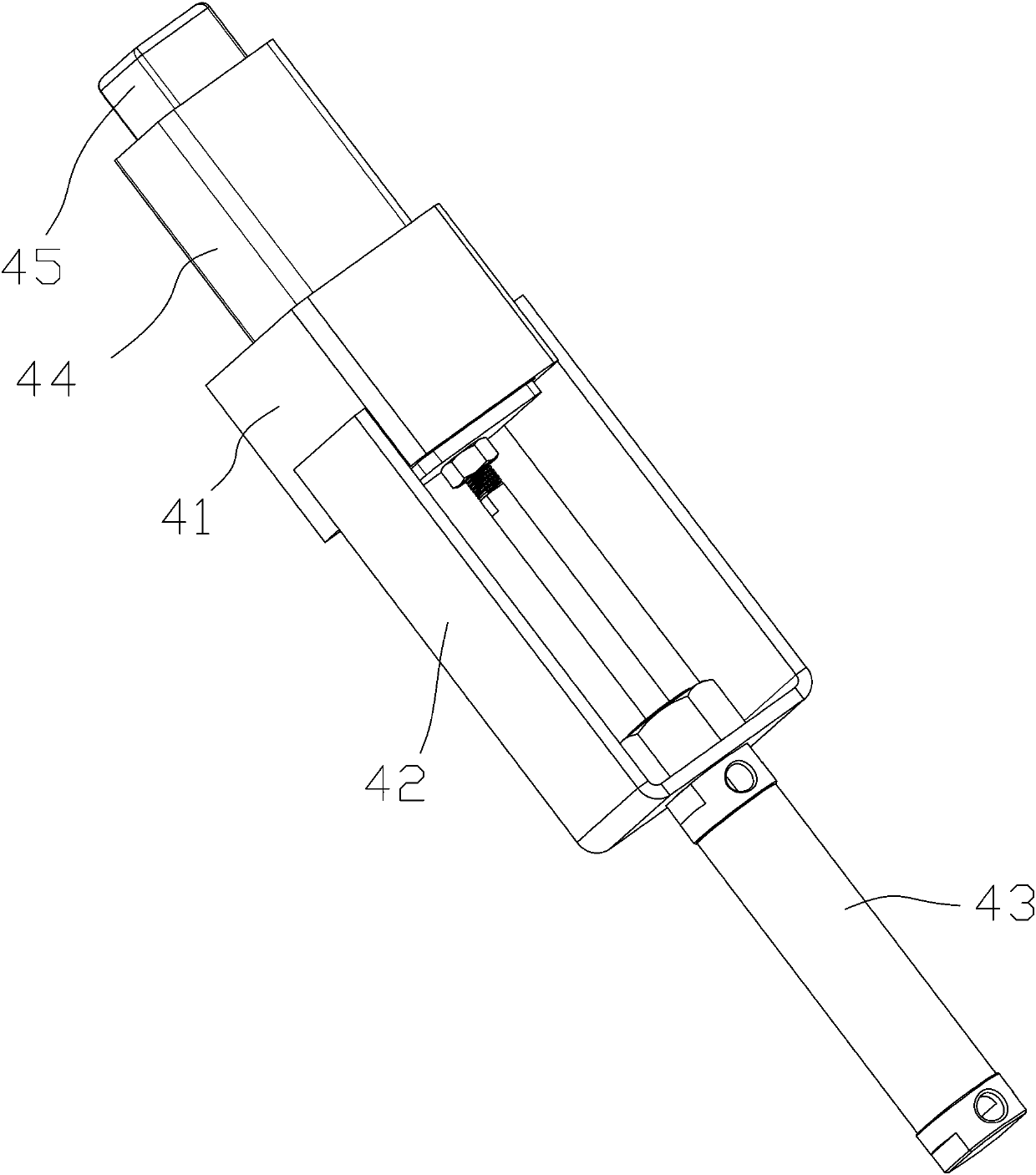
[0026] Depend on Figure 1 to Figure 7 It can be seen that a compact transformer coil winding robot described in this embodiment includes a base plate 1; the base plate 1 is provided with a skeleton feeding mechanism, a fixing seat 2, a feeding mechanism, and a skeleton connected to the fixing seat 2 in rotation. The expansion mechanism, the rotating mechanism used to drive the skeleton expansion mechanism to rotate, the first moving mechanism arranged on the fixed seat 2, the winding arm 3 connected to the output end of the first moving mechanism, and the wire arranged on the winding arm 3 The material mechanism, the tangent bending mechanism located at the winding arm 3, the second moving mechanism for driving the skeleton expansion mechanism to move between the blanking mechanism and the skeleton feeding mechanism, and the skeleton of the skeleton feeding mechanism to move to Th...


PUM


Abstract

The invention relates to the technical field of winding machines, and in particular to a compact transformer coil winding robot which comprises a bottom plate. The bottom plate is provided with a framework feeding mechanism, a fixing base, a discharging mechanism, a framework expanding mechanism, a rotating mechanism, a first moving mechanism, a winding arm, a wire feeding mechanism, a wire cutting and bending mechanism, a second moving mechanism and an ejecting mechanism used for moving a framework of the framework feeding mechanism to the framework expanding mechanism. The coil framework isfixed through the framework expansion mechanism, fixing is stable and reliable, and the situation that the product quality is reduced due to the fact that the framework loosens and shifts in the coilwinding process is prevented; an included angle of 20 degrees is formed between the coil framework and the bottom plate, so automatic feeding and discharging of the coil framework are facilitated, andproduction efficiency is improved; and the wire ends are automatically fixed, so that the problem of poor consistency of manually fixed products is avoided, and meanwhile, the production efficiency is also greatly improved.

Description

Background technique [0001] The patent No. 201811178863.2 proposes a transformer coil winding device, which aims to solve the problem that the skeleton is loose and shifted due to the lack of effective support of the skeleton during the current transformer coil winding process. However, it adopts pneumatic expansion and tightening, and its complex structure is difficult to meet the production needs of small-sized coils. The whole machine adopts a horizontal winding method, which requires manual loading and unloading. Before winding, it is necessary to manually fix the wire and the skeleton, and the production efficiency is low. It cannot meet the needs of large-scale production. Due to the need for manual winding, the product consistency is low, and it is difficult to meet the process requirements of high-precision coil winding. Contents of the invention [0002] The object of the present invention is to provide a compact transformer coil winding robot for the above-mention...

Claims


Application Information

Patent Timeline
Patent Type & Authority Applications(China)
IPC IPC(8): H01F41/06H01F41/082H01F41/096H01F41/098
CPCH01F41/06H01F41/082H01F41/096H01F41/098
Inventor 高天一
Owner 荆门微田智能科技有限公司
Learn More