
Image calibration method and device, electronic equipment and storage medium

A calibration method and image technology, applied in the field of sewing\sewing, can solve the problems of small memory storage space, error-prone, and many steps, and achieve the effect of low time complexity and space complexity, less error-prone, and simple operation

Inactive Publication Date: 2020-04-10
BEIJING DAHAO TECH +1
View PDF4 Cites 5 Cited by
  • Summary
  • Abstract
  • Description
  • Claims
  • Application Information

AI Technical Summary

Problems solved by technology

The difference in thickness mentioned above will lead to poor or even completely unacceptable image calibration accuracy
2. Although the electronic equipment used to control sewing machinery also has chips, memory and other components, compared with high-performance computers, the computing power of the chip is weak, and the storage space of the memory is also small, which is complex for time complexity or space. Algorithms with high degree of support are not enough
The actual operation of Zhang Zhengyou’s calibration method on sewing machines often fails to obtain results within a reasonable time, and may even interfere with the normal work of sewing machines
3. There are many steps in Zhang Zhengyou's calibration method, and it is easy for unskilled people to make mistakes. Once a mistake is made, the whole method must be started from scratch.
Sewing machine operators are usually not familiar with image calibration operations, and it is easy to rework repeatedly, which is a serious waste of time
4. In many cases, the working environment of sewing machinery is not ideal, and there are various problems such as insufficient light, which will affect the accuracy of Zhang Zhengyou's calibration method

Method used


Image

  • Image calibration method and device, electronic equipment and storage medium
  • Image calibration method and device, electronic equipment and storage medium
  • Image calibration method and device, electronic equipment and storage medium

Examples


Embodiment 1

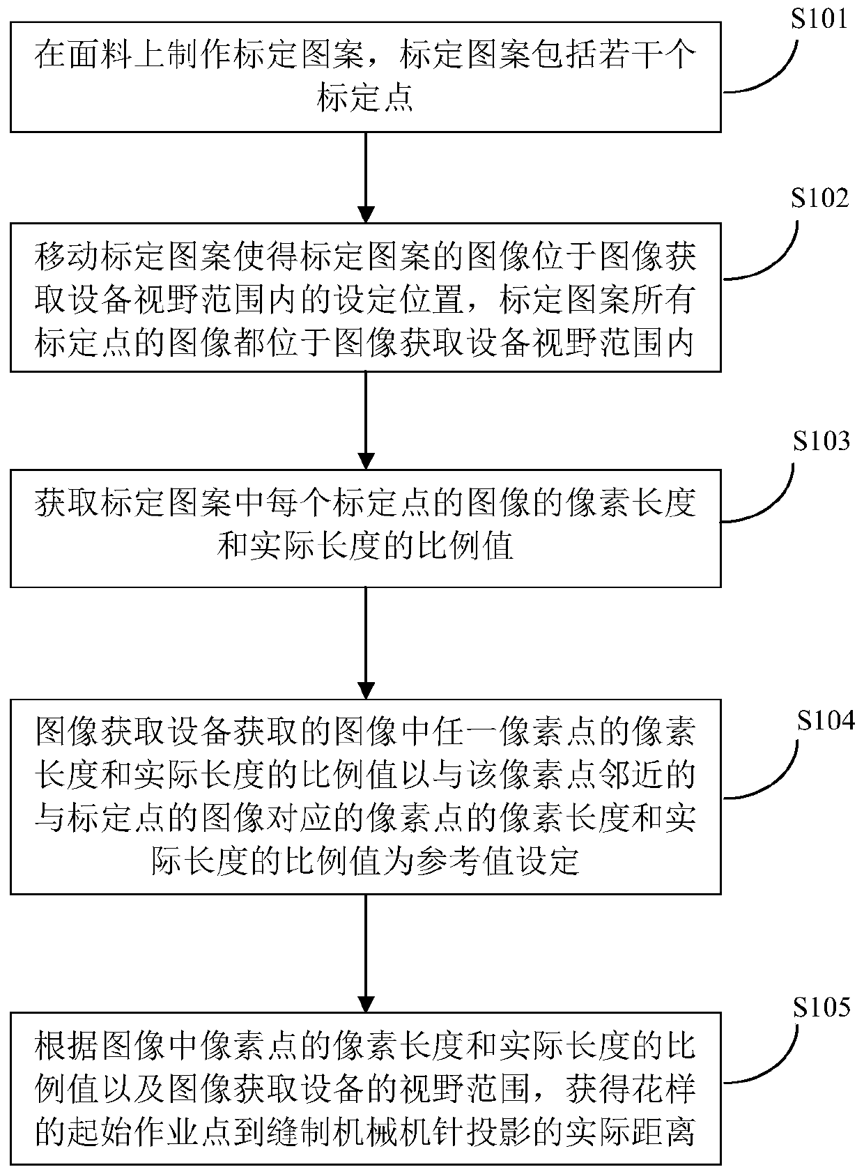
[0049] figure 1 It is a flowchart of the image calibration method in this embodiment, and the image calibration method includes the following steps.

[0050] S101. Make a calibration pattern on the fabric, where the calibration pattern includes several calibration points.

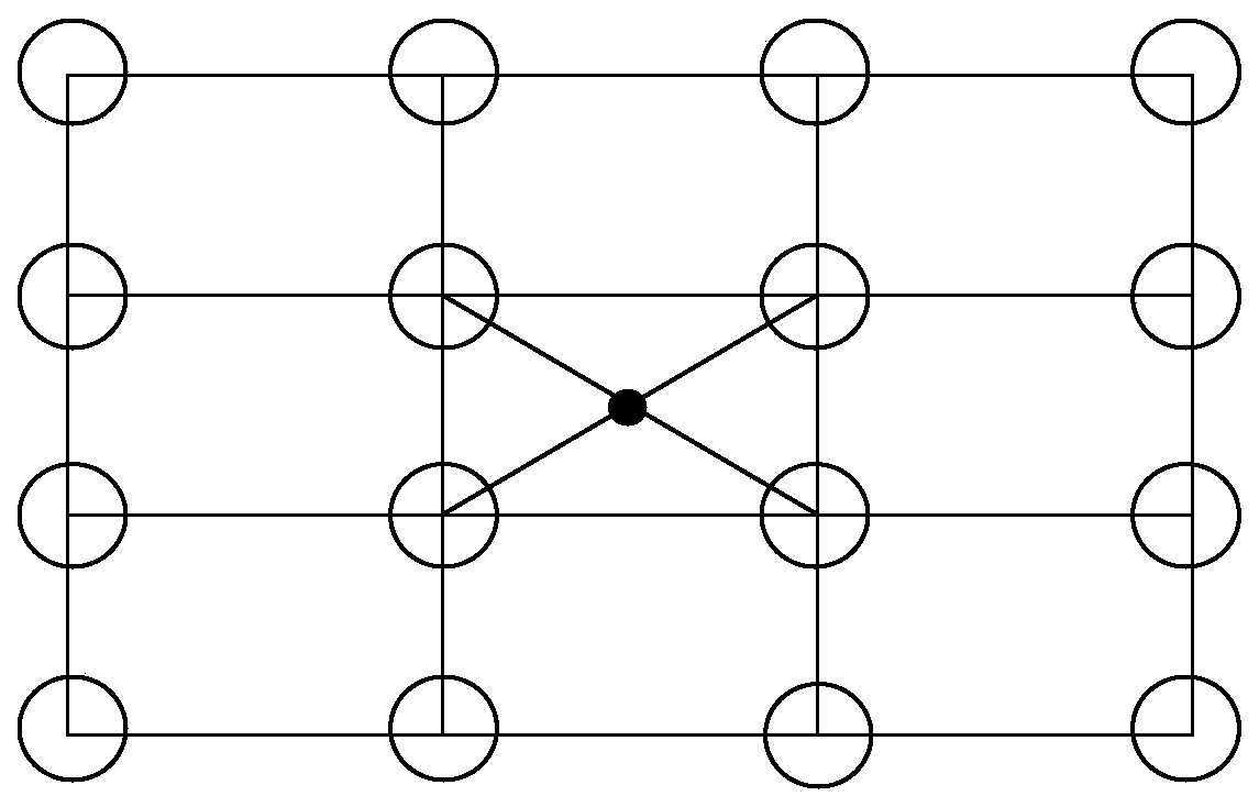
[0051] In this application, a pattern refers to a pattern formed by a real object, and an image refers to an image obtained by an image acquisition device, generally a digital image. In order to perform image calibration correctly, it is necessary to make a calibration pattern on the fabric first. Embroidery machines generally use flat embroidery to embroider calibration patterns on fabrics. Considering the accuracy of image calibration and the convenience of making calibration patterns, calibration patterns usually include several regular geometric figures with the same shape, and special points of regular geometric figures, such as the vertices and geometric centers of geometric figures, are used as cal...

Embodiment 2

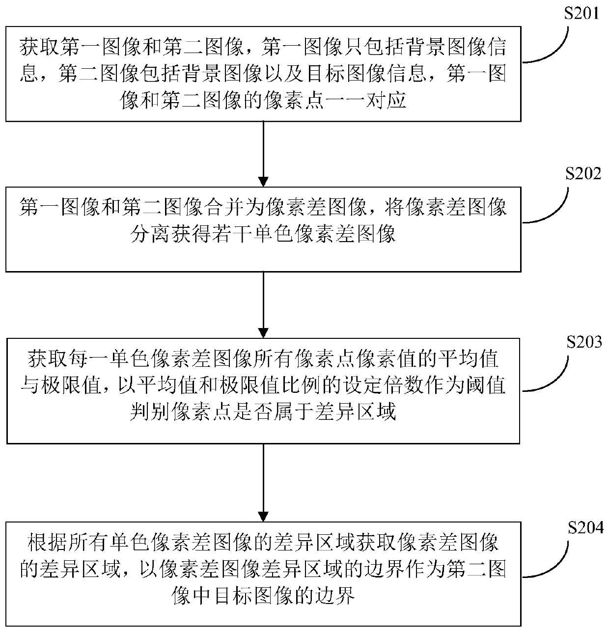
[0070] This embodiment provides a method for recognizing a target image. The image acquired by the image acquisition device is an overall image, only a part of which is the image of the target pattern, and the other part is an unnecessary background image. The recognition of the target image is to extract the target image from the overall image and mark the boundary between the target image and the background image.

[0071] At present, many methods for identifying target images have been reported, such as the widely used GrabGut algorithm. The general steps of the GrabGut algorithm are as follows: 1. Define one or more rectangles containing the target image in the overall image, and automatically define the image outside the rectangle as the background image; 2. Use the Gaussian mixture model (GMM) to compare the background image and the target image Modeling, marking undefined pixels as possible background images or target images; 3. Any pixel in the rectangle is considered...

Embodiment 3

[0089] Figure 4 It is a schematic diagram of the structure of the image labeling device in this embodiment. The image marking device 40 includes a marking pattern making device 41 , a pattern moving device 42 , a proportional value obtaining device 43 , a proportional value setting device 44 and a distance obtaining device 45 . The pattern moving device 42 is used to move the calibration pattern so that the image of the calibration pattern is located at a set position within the field of view of the image acquisition device, and the images of all calibration points of the calibration pattern are located within the field of view of the image acquisition device. The ratio value obtaining means 43 is used for obtaining the ratio value between the pixel length and the actual length of the image of each calibration point in the calibration pattern. Proportional value setting device 44 is used for the pixel length and the actual length of any pixel point in the image acquired by t...


PUM


Abstract

The invention discloses an image calibration method and device, electronic equipment and a storage medium. The method comprises the step of obtaining a proportion value of a pixel length and an actuallength of an image of each calibration point in a calibration pattern, wherein the proportion value of the pixel length and the actual length of any pixel point in the image acquired by image acquisition equipment is set by taking the proportion value of the pixel length and the actual length of the pixel point corresponding to the image of the calibration point adjacent to the pixel point as a reference value. The image calibration method is highly automatic, simple to operate, less prone to errors, low time complexity and space complexity of the algorithm, low in dependence on external conditions such as illumination and the like and particularly suitable for sewing machinery in an actual working environment.

Description

technical field [0001] This application relates to the field of sewing / sewing technology, in particular to an image calibration method, device, electronic equipment and storage medium. Background technique [0002] Sewing\Sewing generally refers to the production process that can form stitches on various materials such as cloth (hereinafter referred to as fabric). Sewing machines, embroidery machines, etc. are all sewing machines. Modern sewing machinery is controlled by electronic equipment and produced according to patterns, which can realize the automation of the sewing process. A pattern is a data file containing production-related data such as sewing image data, and a pattern that can be recognized by a sewing machine can be made by using plate-making software or other software. [0003] With the continuous development of sewing technology, the forms of sewing production are also varied. For example, image acquisition devices such as cameras and cameras can be installe...

Claims


Application Information

Patent Timeline
IPC IPC(8): G06T7/70
CPCG06T7/70G06T2207/30204G06T2207/30124
Inventor 陈可许鹏远郑艳伟徐斌
Owner BEIJING DAHAO TECH
Learn More