
Light curtain target frame body

A light curtain target and frame technology, which is applied in the field of light curtain target frame, can solve the problems of affecting the stability of the optical path, failing to achieve the desired effect, and increasing the cost of reinforcement, so as to reduce structural deformation factors, reduce the difficulty of installation and positioning and Effect of using maintenance difficulty, increasing quality level

Inactive Publication Date: 2020-04-10
SUOOTER TECH BEIJING LTD
View PDF16 Cites 0 Cited by
  • Summary
  • Abstract
  • Description
  • Claims
  • Application Information

AI Technical Summary

Problems solved by technology

Although such a corresponding relationship is reasonable, it is not difficult to install and adjust the transmitter and receiver to realize the quadrilateral optical detection coordinate plane, but the quadrilateral frame structure with the vertical plate as the positioning carrier has problems in transportation, use or disassembly. Misalignment or deformation may occur, affecting the stability of the optical path, thus greatly increasing the reinforcement cost, and even if various reinforcements are carried out, the effect is minimal and the desired effect cannot be achieved

Method used


Image

  • Light curtain target frame body
  • Light curtain target frame body

Examples


Embodiment Construction

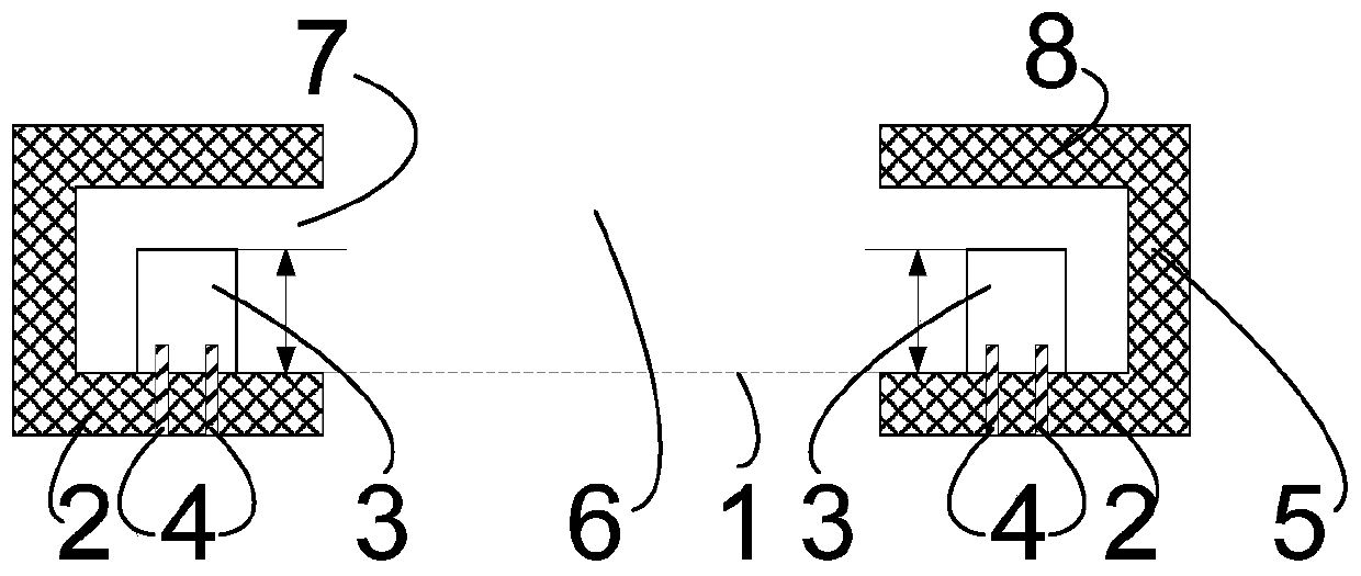
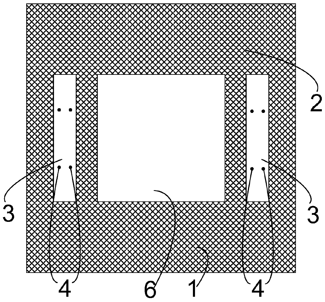
[0018] Below with the accompanying drawings ( Figure 1-Figure 2 ) to illustrate the present invention.

[0019] figure 1 It is a structural schematic diagram of a light curtain target frame implementing the present invention. figure 2 yes figure 1 Schematic diagram of the structure of the upper surface 1 on the bottom plate 2 in . Such as Figure 1 to Figure 2 As shown, a light curtain target frame body includes an integral structure of an annular bottom plate 2 and a vertical plate 5 extending outside the annular bottom plate 2, the upper surface 1 of the annular bottom plate 2 is a reference plane, and the The reference plane is used to install the photoelectric device 3 forming the optical path coordinates, and the hollow part of the annular bottom plate 2 is the target surface installation cavity 6 . The reference plane is connected to the optoelectronic device 3 by installing positioning screws 4 . An annular top plate 8 is provided on the upper edge of the vertic...


PUM


Abstract

The invention discloses a light curtain target frame body. Through a whole structure of an annular bottom plate and a vertical plate extending along the outer side of the annular bottom plate, a photoelectric device forming an optical path coordinate is installed by taking the upper surface of the annular bottom plate as a reference surface, so that a structure deformation factor can be reduced, the mounting positioning difficulty and the use and maintenance difficulty of the photoelectric device are lowered, the optical path is kept stable, and improvement on the quality level of a light curtain target is facilitated.

Description

technical field [0001] The present invention relates to light curtain target technology, in particular to a light curtain target frame, through the integral structure of an annular bottom plate and a vertical plate extending along the outer side of the annular bottom plate, and taking the upper surface of the annular bottom plate as a reference Surface installation of optoelectronic devices forming optical path coordinates can reduce structural deformation factors, reduce the difficulty of installation and positioning of optoelectronic devices and the difficulty of use and maintenance, and keep the optical path stable, thereby helping to improve the quality of the light curtain target. Background technique [0002] The light curtain target generally forms a quadrilateral optical detection coordinate plane through the laser transmitter and the laser receiver. When the bullet passes through the coordinate plane, the coordinate light path will be covered at the point of impact, ...

Claims


Application Information

Patent Timeline
Patent Type & Authority Applications(China)
IPC IPC(8): F41J5/02F41J1/10
CPCF41J5/02F41J1/10
Inventor 方晓青陈洲薄耀旭
Owner SUOOTER TECH BEIJING LTD
Learn More