Automatic swinging air blowing equipment and working method

A working method and equipment technology, applied in the field of fluid dynamics, can solve the problems of shortened life, discomfort of facing the crowd, and waste of manpower and material resources, etc., and achieve the effect of automatic swing of the wind direction

Pending Publication Date: 2020-04-10
NANJING UNIV OF AERONAUTICS & ASTRONAUTICS
View PDF0 Cites 9 Cited by
  • Summary
  • Abstract
  • Description
  • Claims
  • Application Information

AI Technical Summary

Problems solved by technology

However, these blowing devices either only blow in a certain direction, which is likely to cause discomfort to the crowd and cannot take care of the crowd in other directions around; or in order to take care of the crowd in all directions around, it is necessary to install a blowing device with a mechanical swing device
However, this kind of mechanical swinging device itself is a moving part, because long-term work will shorten its life, and it also needs regular maintenance, replacement or addition of lubricating devices, so it will consume a certain amount of manpower and material resources, and the maintenance cost is high.

Method used


Image

  • Automatic swinging air blowing equipment and working method
  • Automatic swinging air blowing equipment and working method
  • Automatic swinging air blowing equipment and working method

Examples


Embodiment Construction

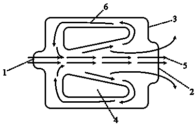
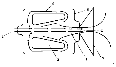
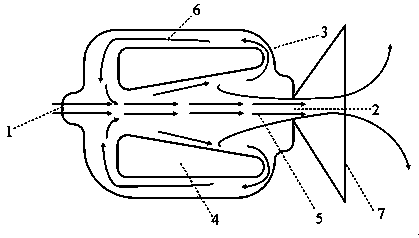
[0024] Combine below Figure 1~3 The operation process of an automatic swing blowing device is described in detail.

[0025] The main flow flows from the air inlet to the air outlet along the axis. As the vertical distance between the edge of the wind deflector and the central axis gradually increases, the pressure at the smaller vertical distance near the air inlet end is smaller, and the vertical distance near the air outlet end is longer. The pressure in the big place is higher, so there is a pressure difference between the two places;

[0026] Due to the closed environment formed by the closed shell, with the effect of the pressure difference, part of the fluid in the main flow where the pressure is higher will flow back along the wind deflector and around the wind deflector to the lower pressure area and disturb the main flow. Due to the non-uniformity of the disturbance, the fluid at the air outlet will gather and swing back and forth within the scope of the restrictor;

[00...


PUM


Abstract

The invention discloses automatic swinging air blowing equipment and a working method, and belongs to the field of fluid dynamics. The automatic swinging blowing equipment is characterized by comprising an air flow inlet, an air flow outlet, a closed shell, wind shields arranged symmetrically and a flow limiting cover. According to the automatic swinging air blowing equipment and the working method, the pressure difference is formed at the upstream and the downstream of the main flow through the special wind shield shape, part of the fluid flows back to disturb the main flow under the action of the pressure difference, and due to the non-uniformity of the disturbance, the fluid at an air flow outlet swings back and forth; the flow limiting cover mounted at the air flow outlet ensures the fluid collection and the swing range of the air flow outlet; and the distance between the tail portions of the wind shields and the closed shell can be controlled by changing the bending radian of theclosed shell, so that the pressure difference is changed to control the flow distribution, and the air flow outlet reaches different air blowing effects. The automatic swinging air blowing equipment and the working method have the beneficial effects that the whole system is free of moving parts, lubrication and maintenance are not needed, the service life is long, and maintenance is avoided.

Description

Technical field [0001] The invention relates to an automatic swing blowing device and a working method, belonging to the field of fluid dynamics. Background technique [0002] In public places such as restaurants and lounges, blowing devices are often arranged to enhance the flow of gas and improve the indoor environment through blowing. It will dissipate heat in the summer and provide warm air for heating in winter. However, these blowing devices either only blow in a certain direction, which is likely to cause discomfort to the crowd and cannot take care of people in other directions around; or in order to take care of people in all directions around, a blowing device with a mechanical swing device is required. . However, this kind of mechanical swing device itself is a moving part, which will shorten its life due to long-term work. At the same time, it also requires regular maintenance, replacement or addition of lubrication devices, which consumes a certain amount of manpowe...

Claims


Application Information

Patent Timeline
IPC IPC(8): F24F13/14
CPCF24F13/14
Inventor 郑明瑞韩东汪胜何纬峰岳晨蒲文灏
Owner NANJING UNIV OF AERONAUTICS & ASTRONAUTICS
Why Eureka
Try Eureka