
Hydraulic system for hydraulic hammer

A hydraulic system and hydraulic hammer technology, applied in the hydraulic system field of hydraulic hammer, can solve the problems of high piling frequency, high requirements for stability and rapidity of reversing, poor reliability, etc., and achieve the effect of improving operation efficiency and maintaining high efficiency and stability

Pending Publication Date: 2020-04-10
上海工程机械厂有限公司 +1
View PDF0 Cites 6 Cited by
  • Summary
  • Abstract
  • Description
  • Claims
  • Application Information

AI Technical Summary

Problems solved by technology

Due to the high piling frequency of the hydraulic piling hammer, the high requirements for the stability and rapidity of the reversing, it is necessary to solve the technical problems of high reversing impact caused by the operation of the hydraulic piling hammer, resulting in a high failure rate of the system and poor reliability.

Method used


Image

  • Hydraulic system for hydraulic hammer
  • Hydraulic system for hydraulic hammer
  • Hydraulic system for hydraulic hammer

Examples


Embodiment Construction

[0046] The present invention will be described in further detail below in conjunction with the accompanying drawings and specific embodiments.

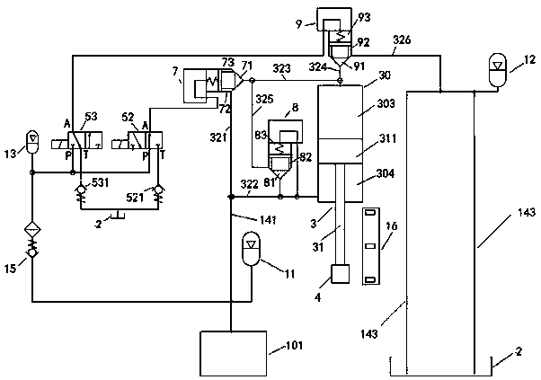
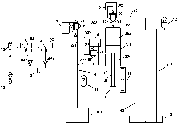
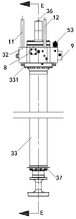
[0047] A hydraulic system of a hydraulic hammer, including a power source 101, an oil tank 2, a lifting cylinder 3, an impact hammer core 4, a second electromagnetic reversing valve 52, a third electromagnetic reversing valve 53, a second cartridge valve 7, a one-way Cartridge valve 8, third cartridge valve 9, second accumulator 11, third accumulator 12, fourth accumulator 13, second check valve 521, third check valve 531, fourth check valve To valve 15, high-pressure pipeline 141, low-pressure pipeline 143, travel switch 16 and control unit, lift cylinder 3 comprises the outer cylinder barrel 33 that contains upper end flange 331, inner cylinder barrel 30, piston rod 31, is positioned at outer cylinder barrel and The annular oil passage 35 between the inner cylinders, the upper hydraulic chamber 303 and the lower hydraulic chamber 30...


PUM


Abstract

The invention discloses a hydraulic system for a hydraulic hammer. The hydraulic system comprises a power source, an oil tank, a lifting oil cylinder, an impact hammer core, a second electromagnetic reversing valve, a third electromagnetic reversing valve, a second plug-in valve, a third plug-in valve, a one-way plug-in valve, a second energy accumulator, a third energy accumulator, a fourth energy accumulator, a second check valve, a third check valve, a fourth check valve, a high-pressure pipeline, a low-pressure pipeline, a travel switch and a control unit, wherein the lifting oil cylinderis positioned in the central pit of a valve block through the inner cylinder barrel and the outer cylinder barrel of the lifting oil cylinder and is fastened with a cylindrical boss; the bottom of theinner cylinder barrel is provided with a plurality of oil holes for communicating a lower hydraulic cavity communicates with an annular oil channel; an upper hydraulic cavity and the lower hydrauliccavity communicate through switching on the one-way plug-in valve; and the second plug-in valve, the third plug-in valve and the one-way plug-in valve are independently installed on installation positions between a first oil channel and a third oil channel, between a fourth oil channel and a sixth oil channel as well as between a second oil channel and a fifth oil channel on the valve block. The hydraulic system has the characteristics of large blow energy, small hydraulic oil reversing pressure fluctuation, a low hydraulic element damage rate, small hydraulic pipeline vibration, high piling efficiency and the like, and is suitable for the high-speed flowing and the timely reversing of hydraulic oil.

Description

technical field [0001] The invention relates to the technical field of hydraulic piling in the field of pile foundation construction, in particular to a hydraulic system of a hydraulic hammer. Background technique [0002] With the continuous development of urban construction, prestressed concrete pipe piles, high-strength concrete pipe piles and steel pipe piles are widely used in foundation projects such as industrial and civil buildings, large bridges, elevated roads, intercity railways and large load-bearing components. Generally, construction equipment such as diesel piling hammer, static pile driver and hydraulic piling hammer are used. Due to the problems of oil fume emission pollution, high construction noise, large surrounding vibration and low operation efficiency during pile sinking operation, diesel piling hammer cannot meet the social development requirements such as low-carbon environmental protection, green energy saving, etc., and its use has been restricted ...

Claims


Application Information

Patent Timeline
Patent Type & Authority Applications(China)
IPC IPC(8): F15B21/00F15B15/14F15B13/02F15B1/02E02D7/10
CPCF15B21/00F15B15/1428F15B15/1457F15B15/1423F15B13/02F15B1/02E02D7/10
Inventor 吴宝山龚秀刚姚国良陈忠强陶雷
Owner 上海工程机械厂有限公司
Learn More